
Alternate format: Cloud network security zones – ITSP.80.023 (PDF, 2.9 MB)
Foreword
This is an UNCLASSIFIED publication issued under the authority of the Head of Canadian Centre for Cyber Security (Cyber Centre).
This document is part of a suite of documents developed by the Cyber Centre to help secure cloud based services. This document supports the cloud security risk management approach defined in ITSM.50.062 Cloud Security Risk ManagementFootnote 1. For more information, email, or phone our Contact Centre:
emailcontact@cyber.gc.ca |Mobile 613-949-7048 or 1‑833‑CYBER‑88
Effective date
This publication takes effect on June 12, 2023
Revision history
- First release: June 12, 2023
Table of contents
- Overview
- 1 Introduction
- 2 Cloud considerations
- 3 Zone interface point (ZIP)
- 4 Cloud zoning guidance
- 5 Cloud edge and perimeter guidance
- 6 Connectivity patterns
- 7 Supporting content
List of figures
- Figure 1: Containers
- Figure 2: Conceptual architecture
- Figure 3: Conceptual architecture in the GC
- Figure 4: Hub and spoke connectivity pattern
- Figure 5: Hybrid connectivity pattern
- Figure 6: Intermediary connectivity pattern
- Figure 7: Data enclave connectivity pattern
- Figure 8: Sidecar pattern
- Figure 9: Ambassador pattern
- Figure 10: Adapter pattern
- Figure 11: API pattern
- Figure 12: Monolithic API gateway pattern
- Figure 13: Specialized API gateway pattern
- Figure 14: API anti-pattern (example 1)
- Figure 15: API anti-pattern (example 2)
- Figure 16: Accessing cloud workloads and use cases
- Figure 17: An example of hub and spoke pattern
- Figure 18: Second example of hub and spoke pattern
- Figure 19: Third example of hub and spoke pattern
- Figure 20: Example of API gateway, API services, and containers
- Figure 21: Relationship between the control and data planes
List of tables
- Table 1: Zone mapping
- Table 2: ZIP security functions
- Table 3: Mapping of baseline requirement and cloud ZIP
- Table 4: Accessing cloud workloads and use cases
List of annexes
Overview
This document outlines cloud network security zone models and architectures and provides technical guidance on implementing cloud network security zones.
The guidance in this document is intended for information technology (IT) solutions within the Government of Canada (GC) operating at UNCLASSIFIED, PROTECTED A, and PROTECTED B levels (i.e. low sensitivity or partial sensitivity). Systems operating in PROTECTED C or classified domains (i.e. highly sensitive) require additional design considerations that are not within the scope of this document. For non-government organizations, the guidance in this document is intended for IT solutions operating with low or partially sensitive information. Your systems operating at higher levels of data classification require additional design considerations and are outside of the scope of this document. You can email or phone our Contact Centre for guidance on cryptographic solutions for PROTECTED C or classified domains.
Your organization is responsible for determining the security objectives that you require to protect information and services. Following only the guidance in this document does not adequately secure an IT environment.
This document is written for IT practitioners who are familiar with the principles, standards, and terminology of network engineering.
1 Introduction
This document provides details on concepts that pertain to network segmentation and zoning applicable to cloud environments and is a companion document to the Cyber Centre’s ITSP.80.022 Baseline Requirements for Network Security ZonesFootnote 2 and its annexes. We recommend you familiarize yourself with the concepts of ITSP.80.022 prior to reading and implementing the guidance in this publication.
Network zoning is the foundation of a defence-in-depth network security strategy and architecture that can support a wide range of security solutions for your organization’s business requirements. For more information on defence-in-depth network security refer to the Cyber Centre’s Network security zoning - Design considerations for placement of services within zones (ITSG-38)Footnote 3 and ITSP.80.022Footnote 2. These security zones also provide a common network infrastructure to support electronic service delivery, interconnectivity, and interoperability. If your organization shares a common infrastructure for online service delivery or other purposes, you must conform to all the security standards established for that infrastructure.
This document describes the architectural design and implementation principles of segmenting a cloud environment into different network security zones. In addition, it details how these principles are adapted and relate to traditional on-premise (on-prem) network zoning. The guidance in this document is mainly applicable to Infrastructure as a Service (IaaS) and Platform as a Service (PaaS). For instance, this document provides guidance on the use of microservices and application programming interface (API) patterns.
The cloud service provider (CSP) is responsible for Software as a Service (SaaS) network zoning of the cloud environment. A PaaS environment is a multi-tenant platform which may be subjected to the CSP network zoning. Your organization is responsible for ensuring that SaaS or PaaS applications comply to your organizational security policy especially on network zoning. The security requirements that a business application must meet are derived from the organization’s security policy or the risk management framework. Also, the Cyber Centre’s IT Security Risk Management: A Lifecycle Approach (ITSG-33)Footnote 4 can be used as part of the risk management framework to determine the security controls your organization should implement. Threat modelling, including identifying specific threats, should be part of your organization’s risk management framework.
Note: You should be aware the guidance in this document will evolve over time due to technological changes. For instance, the guidance provided in section 6 on different usage patterns will evolve as cloud technology evolves.
If you’re implementing IT solutions and your organization is a Government of Canada (GC) department or agency, you must follow all relevant Treasury Board of Canada Secretariat (TBS) policies, including the following:
- Policy on Service and DigitalFootnote 5
- Policy on Government SecurityFootnote 6
- Directive on Security ManagementFootnote 7
GC departments or agencies should also reference to TBS Direction for Electronic Data ResidencyFootnote 8 for data residency requirements detailed in the GC White Paper: Directive on Service and Digital (PDF)Footnote 9. If your organization isn’t a GC department or agency, you can still refer to these policies for additional information.
2 Cloud considerations
As organizational workloads are being migrated to the cloud and the perimeter shifts outside of its on-prem environment, your organization must rethink how it protects and monitors these cloud-based environments. You must also understand how network security zone principles such as those defined in ITSP.80.022Footnote 2 translate into cloud network security zoning constructs.
The principles outlined in ITSP.80.022Footnote 2 are relevant to both the traditional data centre and cloud environments. In a cloud environment, networking has evolved to using software-defined networks (SDN). Compared with traditional networking, SDN has different characteristics and capabilities that need to be taken into consideration when segmenting a cloud environment into different network security zones.
Some of the key differences with traditional networking are:
- decoupling of the control plane from the physical device data plane
- centralized single point of configuration provisioning and management
- central control point for regulating granular security and policy information
You must understand that while the CSP provides management and control plane access to their SDN, that access is exposed through their resource abstraction and control layer similar to a SaaS. The CSP does not provide direct access to their SDN and its implementation whether that is in software or hardware or a part of the CSP fabric.
Both traditional data centres and cloud environments share the same foundational principles of controlling and restricting access and data communication flows to certain components and users. They both establish the network perimeters and their associated boundary defence-in-depth through the following functions:
- Defining the entities that populate zones
- Identifying discrete entry and exit points
- Filtering network traffic at entry and exit points
- Monitoring the state of the network
- Authenticating the identity of network devices and users
- Monitoring network traffic at the entry and exit points
ITSP.80.022Footnote 2 defines several different types of zones. Your organization should understand how these zones translate in a cloud environment. The following table provides a mapping that will be further explored in the remaining sections of this document.
Table 1: Zone mapping
Public zone (PZ)
ITSP.80.022 Traditional networking environment
- Entirely open and includes public networks such as the Internet.
Cloud environment
- Entirely open and includes public networks.
Public access zone (PAZ)
ITSP.80.022 Traditional networking environment
- A PAZ mediates access between operational systems and the PZ that protects the internal network. Extranets connecting via a PAZ are different from those connecting via a restricted extranet zone (REZ) in terms of trust between the partners.
Cloud environment
- The PAZ in a cloud environment has the same purpose. The PAZ in an IaaS and PaaS is more decentralized with several public endpoints. Not all traffic entering and exiting the PAZ passes through a single edge perimeter path. The CSP may provide a number of networking connectivity options for extranets and REZ.
Operations zone (OZ)
ITSP.80.022 Traditional networking environment
- An OZ is the standard environment for an organization’s routine operations. Within an OZ, traffic is generally unrestricted and can originate internally or from authorized external sources.
Cloud environment
- There are similarities and differences between the on-prem and the cloud environment OZs. One of the main differences is that users always reside outside of the cloud environment and access the cloud zones from the on-prem OZ or using PZ.
- It’s possible for both the non-privileged and privileged users to reside on the same on-prem network OZ and access different zones within the cloud environment like the traditional network design.
- Virtual desktops can be provisioned in the cloud environment to meet different business and operational requirements which is similar to having workstations and other devices within an on-prem OZ.
Restricted zone (RZ)
ITSP.80.022 Traditional networking environment
- An RZ provides a controlled network environment, generally suitable for business-critical IT services. An RZ is also suitable for large repositories of sensitive information.
- The current ITSP.80.022Footnote 2 guidance is all accesses to RZ from the PZ is through PAZ and OZ.
Cloud environment
- In a cloud environment, the RZ is configured to meet an organization’s defined baseline security controls based on business requirements and on its function as an RZ.
- In such instances, both non-privileged and privileged users will connect to the RZ from PZ using PAZ to OZ and, if required, to HRZ.
- In addition, a cloud access security broker (CASB) can be used as part of the edge/perimeter services. In this instance, the cloud environment RZ is accessible through the CASB and PAZ from the PZ or on-prem.
Highly restricted zone (HRZ)
ITSP.80.022 Traditional networking environment
- A HRZ provides a tightly controlled network environment designed for enterprise platform, application services and client enclaves that require the highest levels of protection. For example, ones used for highly sensitive information or classified information. An HRZ is also suitable for extensive repositories of sensitive information.
Cloud environment
- Currently the cloud environment is not for HRZs. However, it may be suited for more extensive repositories of sensitive information as defined by the organization’s security policy. Refer to the data enclave connectivity pattern (section 6.5) for more details.
Restricted extranet zone (REZ)
ITSP.80.022 Traditional networking environment
- The REZ may support directly connected extranet services with trusted partners.
Cloud environment
- The CSP typically provides a number of networking connectivity options for REZ. For example, virtual private network (VPN) gateways or private network links that support directly connected extranet services with trusted partners such as virtual network peering and private networking endpoints.
Management zone (MZ)
ITSP.80.022 Traditional networking environment
- The MZ is an isolated zone which is similar in build robustness to an RZ or HRZ. With the MZ, network administrators have a dedicated and isolated administration network for configuring and monitoring network infrastructures. From a security perspective, this zone provides administrators with the capability to perform command and control operations while minimizing the risk of interception or compromise.
- There are two approaches to MZ deployment: isolated MZ and consolidated MZ. The current guidance is to use an isolated MZ approach.
- Refer to ITSP.80.022 - Annex EFootnote 2 for more details.
Cloud environment
- In a cloud environment there is a many-to-one relationship especially when using the consolidated MZ which changes the environment security posture.
- The CSP provides native management services from a SaaS for the organization to configure the cloud native MZ. The security settings for the MZ are the responsibility of the organization to ensure their desired security posture.
- The cloud native MZ provides services such as virtual machine (VM)management. The MZ being integrated within the CSP fabric removes the need for separate network interfaces to manage cloud native resources.
- This has several security benefits that will be further explored in section 4.
3 Zone interface point (ZIP)
ITSP.80.022Footnote 2 defines a zone interface point (ZIP) as a bi-directional system between two zones. The demarcation between zones is called the boundary. The boundary contains ZIPs which are the only connecting points between zones. All data communication between zones must be through a ZIP which exclusively connects these two zones creating a distinct communication path.
A cloud ZIP is a logical construct used to describe the controlled interface connecting two zones. In a cloud environment, there are other logical segregation mechanisms which may not necessarily meet all the security function requirements (see Table 2) of a ZIP, they can have a role in network zoning.
Note: There are two types of ZIPs: MZ-connected ZIP and the data path ZIP. Refer to ITSP.80.022 - Annex FFootnote 2 for more details on these two types of ZIPs. The glossary (section 7.2) also includes definitions for these two ZIPs.
Some of the concepts in this section are specific to how CSP have implemented security compared to the legacy on-prem methods. However, these concepts are part of a defence-in-depth strategy which is typically not available in a traditional networking environment or described in ITSP.80.022Footnote 2. In cloud-native environments, a strong security posture is closely tied to identity and access management (IAM). The cloud MZ IAM service requires the organization to implement role-based access control (RBAC) to control permissions for users and resources. RBAC should be structured to enforce least privileged access. The least privileged access (LPA) principle and the impact of applying it correctly greatly increases security and reduces risk. The goal of LPA is to ensure all users should log on with a user account that has the absolute minimum permissions necessary to complete their current task and nothing more.
In a cloud environment, the MZ IAM service provides the highest level of logical segregation in the form of a top-level account. A top-level account would be similar in concept to a domain administrator or a root level account in an on-prem environment. The top-level account can further provision sub-accounts to organize the cloud RBAC into a hierarchy similar to groups in a directory service. This structure can be leveraged to enforce policy between sub-accounts or groups of sub-accounts within the hierarchy. This can provide basic security functions such as access control, authentication, and traffic filters.
Within a top-level account (the foundational cloud networking construct) is the virtual network which provides logical zoning. These virtual networks require security services, such as virtual network peering and networking gateways, for traffic filtering and access control.
The following table provides the definitions of the security functions associated with a ZIP as defined by ITSP.80.022Footnote 2.
Table 2: ZIP security functions
- Security Function
- Description
- Access control
- Controls traffic based on the source and the destination addresses and the type of service.
- Entity authentication
- Validates the authenticity of entities (person and nonperson entity accounts) and establishes a security association between them.
- Data origin authentication
- Validates the authenticity of the entities participating in a security association.
- Data integrity verification
- Verifies that network traffic has not been modified or replayed.
- Traffic filters
- Filter or block traffic based on properties of the data communications stream, including:
- transmission control protocol (TCP) state
- source and destination, conformity with authorized communications protocols
- data types embedded within the data communications stream
- contents of the data communications stream
- Intrusion detection and audit support
- Provide the services and attributes that support the implementation of security functions, such as intrusion detection, audit, and incident response. CSPs are providing this capability across their cloud environment and not only limited to the ZIP.
- Resource encapsulation
- Refers to the mechanisms that allow the zone to hide its internal structure. These mechanisms include network address translation, port address translation, and service mapping. Resource encapsulation supports access control and survivability.
Within a cloud environment, there are several security constructs that fulfill some or all of the security functions and requirements. Depending on the CSP, we can expect a variation in these constructs and capabilities. Your organization should consult the CSPs’ technical documentation. Common examples of cloud-native security services that can be built into CSP policy rules include the following:
- geo boundaries
- multi-factor authentication (MFA)
- trusted or blocked locations
- partners trust controls
- advanced identity risk detection and protections
- trusted or blocked devices
- trusted or blocked software
- trusted or blocked operating systems
- cloud defined entry points.
A virtual ZIP instance should not contain both MZ-connected and data path ZIPs. Any virtual instance of the MZ-connected ZIP or the data path ZIP should meet the assurance requirements derived from your organization security policy and risk management framework. Refer to Table 1: Zone mapping in section 2 for more details on MZ and other zones.
Network zoning is used to subdivide a network into subnets or zones which have the same security policies and security requirements. Organizations should implement network security zoning to achieve their defined network security strategy. Implementing zoning may prevent or impact a threat actor from gaining lateral movement on the entire network. Zoning logically groups data, software, or hardware with similar security policies and security requirements.
Note: Network segmentation refers to a networking technique that divides a network into smaller, distinct sub-networks. It enables organizations to compartmentalize the sub-networks and deliver unique security controls and services to each one. Network security zones are logical grouping based on the underlying implementation of network segmentation. The unique security controls protecting a zone are defined within the ZIP.
Cloud resources are deployed within these specific zones. In a traditional network environment, we would expect to find a ZIP at the boundary of the zone. Within a cloud environment, there is some additional capability whereby a ZIP can be situated at the boundary of a zone or can also be within a zone associated with specific cloud resource network interfaces such as a VM or host.
In this document, a ZIP at the edge of the zone will be referred to as a network access control list (NACL) and a ZIP within a zone will be referred to as a network security group (NSG). Both are cloud-native constructs. In terms of network access control, the NACL is stateless while the NSG is stateful.
In Cloud deployments, we consider both cloud native and third-party next generation firewalls (NGFW) that are located at the boundary of a zone. Organizations that are currently using NGFW on-prem may choose to deploy the same NGFW solution within the cloud infrastructure to reuse operational knowledge, tooling, and ensure supportability. In this document we assume that the NGFW can be configured to meet all the security functions of a ZIP. We make the following distinction between a traditional firewall and a NGFW. A traditional firewall typically provides stateful inspection of all network traffic while a NGFW includes additional features such as application awareness and control, integrated intrusion prevention, and cloud-delivered threat protection and intelligence. For instance, a web application firewall (WAF) should be used to filter malicious traffic to the application and placed in front of either the web server or the application RZ. A database RZ ZIP should include a database audit and protection (DAP) device to filter malicious structured query language (SQL) queries and monitor database activities.
There is a general trend that several of the traditional security functions and requirements associated with a ZIP such as intrusion detection and audit, access control, and traffic filters are natively embedded on the CSP fabric and are not just reserved or associated with ZIPs. The CSP identity and access is embedded within the fabric and provides native security function such as intrusion detection (threat detection) and audit (audit logs). Security functions such as Data Origin Integrity and Data Integrity Verification are also being integrated within the CSP fabric across the cloud environment.
Refer to Annex A for more details on the mapping of ZIP security objectives and how ZIP baseline security requirements to the cloud ZIP are defined. You can also refer to Annex A for additional details on how to leverage ZIPs based on your organization’s security requirements.
4 Cloud zoning guidance
This section provides cloud zoning guidance as it relates to the management zone, containers, and application APIs.
Cloud zoning should include an overarching strategy to ensure secure access and management of cloud resources. Logical segmentation is used to implement this strategy and consists of using zoning to segment the cloud environment into distinct logical zones. Cloud management is part of the cloud control plane and is used to provision and provide ongoing support for cloud resources including configuring virtual networks and virtual network zoning. APIs can be used to perform management tasks as part of the control plane.
Cloud network segmentation should be part of a defence-in-depth strategy. Refer to Table 1: Zone mapping in section 2 for the different types of zones that can be leveraged. The principle of least privilege should be applied to reduce the cloud attack surface by preventing for instance a threat actor from gaining lateral movement to other zones.
Communication between cloud resources in different zones should be restricted to only authorized traffic and mediated by a ZIP thereby further reducing the cloud attack surface and blast radius. A PAZ should be designated as the external access point for network traffic to and from cloud resources. Refer to section 6 - Connectivity patterns for more information about patterns that can be leveraged.
4.1 Segmentation
This section provides guidance on segmentation in cloud deployments including internal zoning and connectivity. In traditional data centres network segmentation is a technique that divides a network into smaller, distinct sub-networks that allow the organization to compartmentalize data, systems, and traffic in them. Network security zoning is used to mitigate the risk of an open network by segmenting infrastructure services into logical groupings that have the same communication security policies and security requirements. Segmentation, based on the traditional data centre, has evolved since the wide adoption of cloud computing. Software automation tools, such as orchestrator and SDN, can be used to implement segmentation as part of cloud management.
Segmentation prevents threat actors from gaining lateral movement between the different zones within the cloud environment. For instance, the compromise of a workload in one zone by a threat actor doesn’t result in the compromise of other workloads in other zones within the cloud environment. It reduces the blast radius of a successful attack.
The cloud blast radius is reduced as more granular zones are defined and implemented which should be part of your organization segmentation strategy. Each zone in a cloud environment should be allocated separate compute, network, and storage resources. For instance, the control and data planes should reside in different zones and be allocated separate resources. As part of cloud segmentation, the control plane is part of MZ while the data plane is part of either data or application RZ.
As part of a defence-in-depth strategy, segmentation is used to restrict access to internal cloud zones from the public zone. A PAZ should be designated as the only external access point for all traffic flows and these flows should be mediated by a ZIP. Controls for traffic flows within a zone and between the zones are implemented based on your organization’s security policy. It may be possible that your organization’s security policy is part of your organizational enterprise security design and data flow security policies.
In addition, the principle of least privilege should be applied to network segmentation. Communications between workloads within the same zone and between different zones should be restricted to authorized traffic flows and paths. The application of this principle is important when provisioning network access permissions for privileged and non-privileged users. For instance, this principle is applied when granting access for privileged users to management interfaces on the control plane and access permissions for unprivileged users to workloads on the data plane.
SDN enables the abstraction of cloud resources and the decoupling of the cloud control plane from the data plane. SDN is embedded within the cloud environment and is invisible to both non-privileged and privileged users. In terms of size, the data plane is much larger compared to the control plane sometimes by orders of magnitude. The adapter pattern can be used, as part of segmentation, to handle the traffic flow between the two planes (refer to section 6.7 - Adapter pattern).
4.2 Cloud management
In Cloud environments, The CSP provides native management services from a SaaS portal for the organization to configure the cloud-native MZ, the security settings for the MZ are the responsibility of the organization to ensure their desired security posture.
The traditional MZ is being replaced and integrated within the CSPs fabric. In addition, the MZ usage is mitigated by compensating security controls that are usually provided by the CSP, your organization will need to configure the security controls to ensure the desired state security posture. The management tasks that are accessible on a per Cloud Resource further reduce the attack surface and blast radius compared to using a MZ to access all cloud resources within a particular zone.
Using the current trend, management access isn’t provided via traditional public endpoints and management ports which can significantly reduce the cloud environment visibility to threat actors. Instead, secure connectivity is first initiated from the CSP environment to the authorized management endpoint which then enables the authorized management endpoint to use the established secure networking connectivity to perform management tasks to the specific cloud resource. This is the recommended guidance in a cloud environment.
In addition, it’s recommended that an identity and privileged access solution be used to secure the management accounts used to perform the privileged tasks. This solution should be secured for instance using multi-factor authentication.
4.3 Containers
In a traditional 3-tier application architecture, an application is divided into web, application and database tiers with each tier having its own compute, network, and storage resources within segregated zones. Your organization should consult ITSG-38Footnote 3 for additional guidance.
In a microservices architecture, an application is divided into many sub-components. Each sub-component typically has a single well-defined function which consists of a single process and runs in its own separate container. A single container process provides process isolation. By default, traffic flows between containers are unrestricted. We will provide guidance on how to restrict these traffic flows in this section.
One of the key differences between containers and VMs is the former consists of a single process likely running on a VM, while the latter runs an application and its dependencies (if applicable). For instance, one or more containers can run within a single VM or operating system (OS) kernel. Another example is a container with high classification data running on its own VM with proper zoning and other security controls while several containers with low classified data reside on an OS kernel.
Containers abstract OS kernel and hardware-specific resources and have all the necessary business logic, configuration, and dependencies to enable them to execute during runtime.
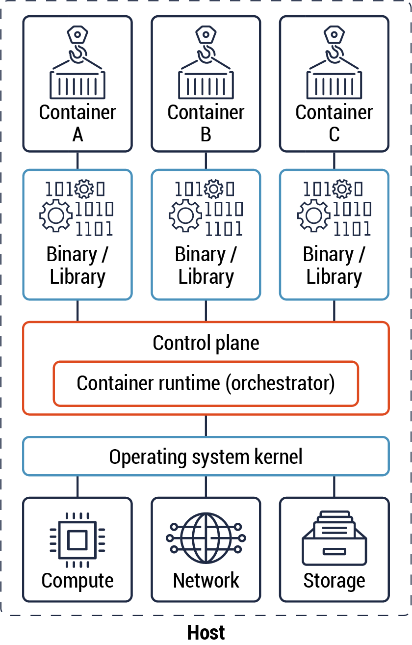
The diagram below (Figure 1) illustrates three containers, their dependencies, and the control plane.
Figure 1: Containers
Long description - Containers
Figure 1 consists of four segments, each containing individual boxes to represent the process of containers. The image illustrates three containers, their dependencies, and the control plane. There are three containers shown labelled A, B, and C. Each container feeds into a separate binary/library. Each container is used to run a single process, that is generated from a well-defined function.
The containers will abstract OS kernel and hardware-specific resources and execute them during runtime. This is depicted in the diagram in the third segment shown in a box labelled “Control plane – Container runtime (orchestrator).
The last segment in the image represents the process in which an application is divided into web, application, and database tiers with each tier having its own compute, network, and storage resources within segregated zones.
Containers which have different functions should be segregated in different RZs based on data classification and sensitivity levels . For instance, containers that host an application and a database that form a part of a solution should be placed in different RZs. A container orchestrator can be used to manage the deployment of containers and ensure that the principle of least privilege is applied to both ingress and egress traffic flows between containers. The orchestrator is considered part of the cloud control plane, and, in this instance, it’s used to enforce zoning. Refer to Annex D, Figure 21 for the relationship between the control and data planes.
The principle of least privilege should be applied to traffic flows between containers on the same kernel, network zone and in different zones. By default, an explicit deny-all rule should be enforced and access should be granted by exception. For instance, known communications between different containers, which form a microservice, should be allowed.
Zoning should be used to restrict access to the containers and microservice by using granular access controls. Communication between different containers in the same zone (not part of the same microservice) or different zones should be restricted and only allowed where necessary. Refer to section 4.5 for more details on granular access control.
Zoning is important in terms of both ingress and egress traffic flows. Both types of data traffic flows should be restricted using appropriate mechanisms such as a ZIP to enforce zoning.
Below are three (3) use cases that arise in container segmentation and zoning:
- Containers should be segmented based on their relative security context to ensure that a given system kernel only runs containers with the same data sensitivity and functionality. For instance, containers that consist of a single microservice can share the same compute, network, and storage resources.
- Containers with different functionality but the same security context or data classification should be segregated. In this instance, the different containers should be grouped in the same zone and segmented from each other by allocating different resources. For example, public-facing and internal applications should be placed on different virtual networks and communication between the two networks should occur through a small number of well-defined interfaces depending on your organization’s security policy.
- You should segregate containers with different data classifications in different zones and should use different compute, network, and storage resources. Containers with a higher data classification should be placed on a different RZ with different resources compared to containers with lower data classification. For instance, you can use an orchestrator to isolate containers to specific sets of hosts based on sensitivity levels.
In most cases, you can define the rules that prevent your organizational high sensitivity workloads from being placed on the same host with lower sensitivity workloads. This can be accomplished by having separate, individually managed clusters for each sensitivity level. Alternatively, you can use the orchestrator to do host “pinning” whereby a container is assigned a specific host. You should be aware that host “pinning” will result in the container being unavailable if the host is unavailable.
The use cases for containers are constantly evolving. For example, deploying a database in a container is a use case that is still maturing. There are specific examples where this is an acceptable practice. For instance, this practice can be used in a non-production cloud environment such as a test or development environment. In all use cases, sound zoning principles should be adhered to such as placing these containers in a Data RZ.
4.4 Application programming interface (API)
The shift to cloud environments and, in particular microservices architecture, has resulted in microservices communicating using well-defined APIs. Most, if not all, of the cloud environment software components offered by CSPs are API-based. APIs are part of cloud automation tools such as orchestrators and SDN. You can use APIs to expose your organization’s data and services to external entities and users. In addition, access to the APIs should be secured and restricted to specific zones and workloads.
Within a cloud environment, APIs can be deployed in different network zones depending on your organizational business requirements. For instance, APIs can be deployed as edge services as part of the PAZ, cloud control plane and data plane in the cloud environment. Also, APIs can be deployed within the same zone as the microservice or on the on-prem network. Cloud-native tools and web consoles can be used to make API calls to manage the cloud environment resources and to make requests to a microservice. In a traditional data centre, workstations are sometimes used to perform administrative tasks on servers and hardware management platforms, among others.
Below are some use cases for the use and placement of APIs to provide segmentation:
- APIs can be used to mediate traffic flows between the control plane, data plane and the backend application such as a legacy application or end-of-life database. In this instance, the API should be placed in the data plane and as close as possible to the workload. Refer to section 6.6 - Container pattern for more details.
- APIs can be used to mediate traffic flows between the cloud environment and an on-prem network or the public zone. The API is placed in the cloud environment PAZ as part of the edge services. This is the only entry point to the microservices for all requests that originate from external sources. Refer to section 6.9 - API pattern for more details.
- APIs are used to perform management tasks as part of the control plane. For instance, privileged users use an API to manage the compute, network, and storage resources. Refer to section 6.9.1 - API gateway pattern for more details.
- You can use APIs to provide network connectivity to the data plane and connectivity between different components within this plane. For instance, the API, in the form of proxies, is used to provide connectivity between the microservices in the application RZ and to provide operational status to the control plane. Refer to section 6.6.2 - Ambassador pattern for more details.
In addition, APIs can be used to implement an organizational security policy. For instance, an access control policy API can be used to restrict access to microservices. In this instance, the policy API is used to enforce access control for both ingress and egress traffic flows to the microservices. In terms of the ingress traffic, the API is used to restrict inter-container traffic flows. For egress traffic, the API is deployed at the cloud environment edge to enforce access control authorization based on clients’ requests. Refer to section 6.6 - Container pattern for ingress traffic access control. Also, refer to section 6.6.2 - Ambassador pattern and section 6.9.1 - API Gateway pattern for more details on egress traffic access control.
4.5 Access control
Access to microservices and APIs should be restricted to authorized users and resources using granular access controls. Some examples of these access controls include using segmentation, authentication, and authorization. All communications within a zone and between zones should be secured using TLS 1.2 or higher in accordance with the Cyber Centre’s guidance.
To secure ingress traffic between microservices, you should use peer authentication and request authentication. Peer authentication is used for service-to-service authentication to verify the client making the connection. The client and server should use a TLS certificate to identify themselves to each other. It also protects communications between two parties by providing confidentiality and integrity. Request authentication is used to verify the end user credential attached to the request. This is used when a request is made from the client to the server on behalf of an end user.
All service requests should be authenticated and authorized before access is granted. API keys and open standards such as Open Authorization 2.0 (OAuth 2.0) should be used to secure service requests. API keys should be stored securely, and their access should be restricted. Refer to Government of Canada Standards on APIsFootnote 9 for more details on how to secure APIs and cloud services. For more information, see ITSP.40.062 Guidance on Securely Configuring Network ProtocolsFootnote 10.
5 Cloud edge and perimeter guidance
The cloud environment is changing the traditional definition and role of the network edge or perimeter. The cloud environment offers a more decentralized environment, and by extension, its edge is more decentralized. For instance, the cloud environment has many public endpoints that are associated with the various CSP’s IaaS and PaaS services. There are usually corresponding private endpoints which enable the use of these cloud services within a virtual network while still adhering to network zoning principles.
This illustrates the challenges of securing the edge or perimeter in a cloud environment and the importance of zoning in terms of both ingress and egress traffic flows. Both types of data traffic flows should be restricted using appropriate mechanisms, such as a ZIP, to enforce zoning. In addition, container orchestrators and virtual networking technology can be leveraged to enforce department security policies for both traffic flows.
Depending on the connectivity pattern being used, the CSP will manage the cloud edge. There may also be additional intermediaries (section 6.4) such as managed security service provider (MSSP) that offer security services or CASB that further extend the edge/perimeter.
5.1 Use cases and guidance
In the cloud, an environment is a virtual network unto itself. In this section we will look at how we can leverage our connectivity patterns and extend the virtual network by integrating it with other virtual networks. In the subsequent section, we will look at how we can leverage our connectivity patterns within a virtual network as part of cloud zoning.
Below are some use cases and corresponding guidance:
- Use case: Another virtual network within the same top-level account
- Guidance: Two virtual networks within the same top-level account can be integrated in terms of network connectivity leveraging the CSPs networking services such as virtual network peering or networking gateways. Some of these networking services provide security functions for network traffic filtering and access control.
- These networking services, in most instances, don’t meet all the security functions and requirements of a ZIP and should be augmented with the integration of a ZIP. The ZIP should be associated with the PAZ in both virtual networks for both ingress and egress traffic.
- The guidance is to leverage the hub and spoke pattern where each application virtual network is within a spoke. The ZIP can be implemented within each of the spokes’ virtual networks and the hub based on organizational security requirements and policy. Refer to section 6.2 – Hub and spoke pattern, including Figure 2: Conceptual architecture, for more details on the hub and spoke pattern.
- Use case: Another virtual network in a different top-level account within the same cloud region
- Guidance: Most CSPs provide intra-regional services that can be leveraged which enable the integration of virtual networks across different top-level accounts. Therefore, the guidance provided in the previous scenario is also applicable in this use case namely the use of the hub and spoke pattern.
- Use case: Another virtual network in a different top-level account in a different cloud region
- Guidance: Most CSPs provide inter-regional services that can be leveraged which enable the integration of virtual networks across different top-level accounts in a different region. Therefore, the guidance provided in the previous scenario is also applicable in this use case namely the use of the hub and spoke pattern.
- Use case: Another virtual network in a different top-level account with a different CSP
- Guidance: Currently, CSPs don’t offer inter-CSP networking connectivity via their backplane. This leaves two networking options namely leveraging the PZ or on-prem network.
- Public Zone. We can leverage either direct Internet-to-Internet connectivity or we can leverage a site-to-site VPN. In both use cases the termination should occur within the PAZ. You should leverage the guidance in section 6.2 – Hub and spoke pattern and section 6.4 - Intermediary connectivity pattern and terminate connectivity within the hub PAZ that acts as ZIP.
- On-prem. The assumption is that the organization has established a dedicated network connection between the organization’s on-prem network and the two CSP’s regional data centres via a CXP. This dedicated network connection should leverage security functions such as IPsec VPN, OSI Layer 2 encryption and TLS encryption . You should leverage the guidance in section 6.3 – Hybrid connectivity pattern. If the same CXP is used for both CSPs it may be possible to route network traffic directly from the CXP without first having to go on-prem from CSP (i.e. cloud to ground) and then having to send this traffic from the on-prem network to the second CSP (i.e. ground to cloud).
- Guidance: Currently, CSPs don’t offer inter-CSP networking connectivity via their backplane. This leaves two networking options namely leveraging the PZ or on-prem network.
- Use case: On-prem network
- Guidance: The assumption is that the organization has established a dedicated network connection between the organization’s on-prem network and the two CSP’s regional data centres via a CXP. This dedicated network connection may leverage additional security functions such as IPsec, MACsec and TLS. You should leverage the guidance in section 6.3 – Hybrid connectivity pattern.
6 Connectivity patterns
In this section, we will look at cloud design patterns for zone selection and implementation which we will leverage in the subsequent sections. A pattern is a collection of reusable solutions and design ideas for using technology to solve common systems design problems. It shows an end-to-end data flow between system components or zones.
Design patterns are useful as they usually represent established solutions to common design problems and are generally repeatable. They are organized into a standardized referenced format and can be used to ensure consistency in how systems are designed and implemented. Their use does not guarantee that design problems are always solved as many factors come into play including client security requirements and constraints.
The cloud connectivity patterns we will look at are CSP agnostic. The patterns covered in this section are documented where applicable as follows:
- Pattern name and a short description of the pattern
- Brief explanations of the challenges that can be solved through the implementation of the pattern. This can take the form of a requirement.
- Visualization of the pattern structure, including the design solution proposed by the pattern to solve the problem and fulfill the requirements
- Guidance on how the pattern can be applied, including guidelines, benefits, use cases, advantages, and disadvantages
The following are the patterns covered in this section:
- Hub and spoke pattern
- Hybrid pattern
- Intermediary pattern
- Data enclave pattern
- Container patterns
- Adapter pattern
- API and Anti-API patterns
6.1 Conceptual overview
Before we look at and reference individual patterns, the following diagram provides us with a conceptual overview of some of the key patterns and how they may be leveraged. Refer to Annex B for more details.
Figure 2: Conceptual architecture
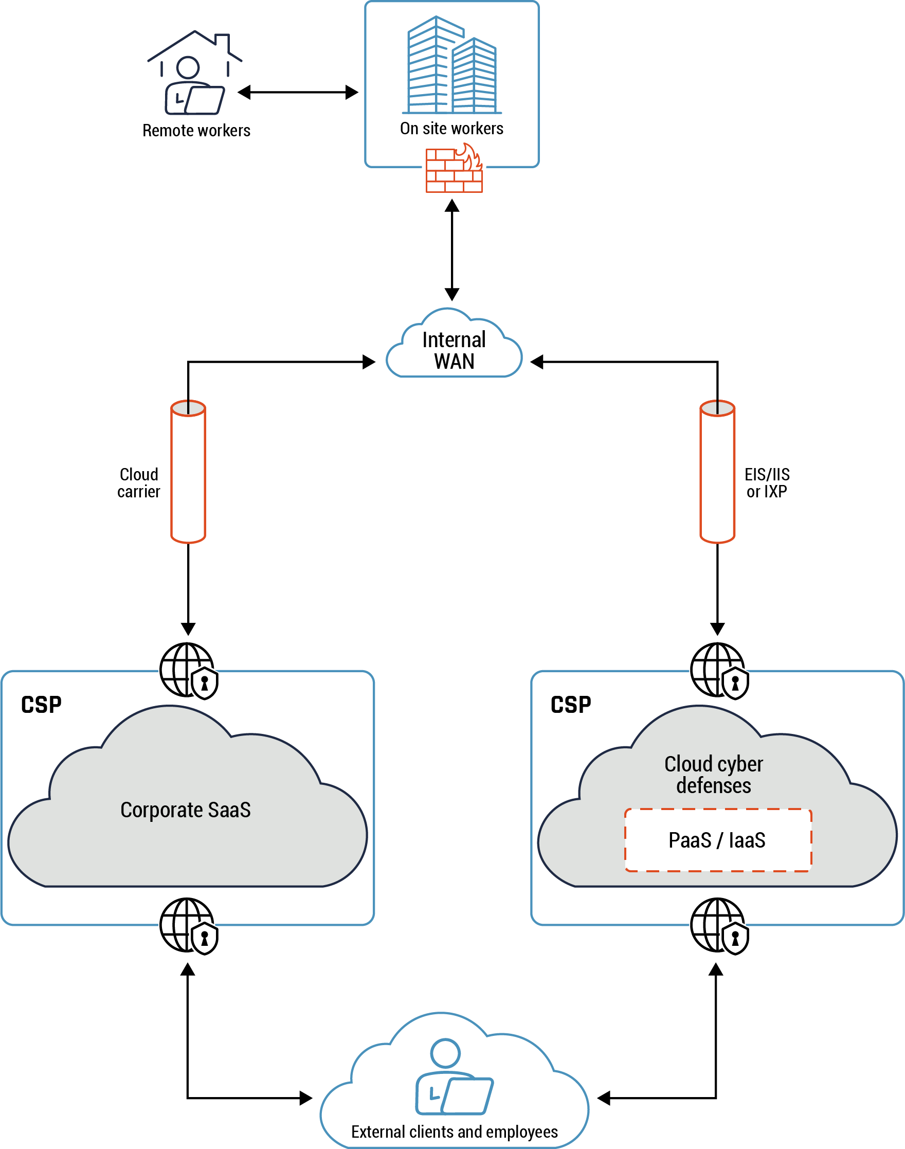
Long description - Conceptual architecture
Figure 2 provides an overview of the conceptual architecture view. The diagram shows a remote user connecting to the on-premise workplace via a virtual private network (VPN). Under the icon representing the on-premise work place is firewall icon to highlight that traffic flows through the firewall to the internal WAN, which is represented by a cloud icon.
There are two tubes connected to the WAN cloud icon to represent the flow of traffic and data from the from the WAN to the cloud carrier via an EIS/IIS or an IXP. Traffic and data continues to flow from the cloud carrier to the corporate SaaS cloud provided by the CSP, represented by a cloud icon with a secure entry and exit point in the diagram. Traffic and data flows from the EIS/IIS or the IXP to the PaaS or IaaS through cloud cyber defences hosted by the CSP, represented with a secure entry and exit point in the diagram. Traffic from both cloud platforms, SaaS or PaaS or IaaS, is then delivered to external clients or users, who are represented as an icon of a person working in front of a laptop.
Figure 3: Conceptual architecture in the GC
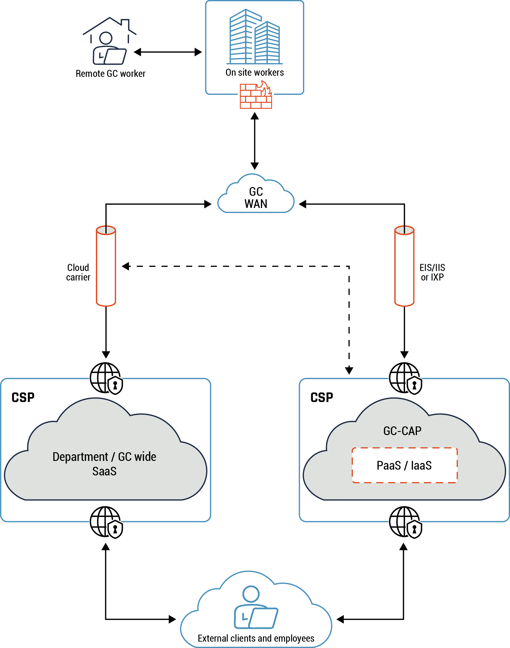
Long description - Conceptual architecture
Figure 3 provides an overview of the conceptual architecture view within the GC. The diagram shows a remote user connecting to the on-premise workplace via a virtual private network (VPN). Under the icon representing the on-premise work place is firewall icon to highlight that traffic flows through the firewall to the internal GC WAN, which is represented by a cloud icon.
There are two tubes connected to the GC WAN cloud icon to represent the flow of traffic and data from the from the WAN to the cloud carrier via an EIS/IIS or an IXP. Traffic and data continues to flow from the cloud carrier to the Department or GC-wide SaaS cloud provided by the CSP, represented by a cloud icon with a secure entry and exit point in the diagram. Traffic and data flows from the EIS/IIS or the IXP to the GC-CAP (PaaS or IaaS) through cloud cyber defences hosted by the CSP, represented with a secure entry and exit point in the diagram. Traffic from both cloud platforms, SaaS or PaaS or IaaS, is then delivered to external clients or users, who are represented as an icon of a person working in front of a laptop.
The conceptual architecture view provides a high-level view into some of the most common key connectivity patterns such as the hybrid, intermediary, and hub and spoke. Traffic entering and exiting the cloud environment originates from the CSP’s many public endpoints. A hub and spoke pattern is at the core of the networking and zoning architecture. The hub hosts common or shared services such as monitoring, routing and inspection. These services can be consumed by the different workloads hosted in the spokes. In addition, it mediates and inspects all traffic between the PZ, your on-prem network and your cloud environment.
Your organization’s cloud workloads are deployed in the spokes. A spoke can be segmented into different zones such as web, application, and database tiers with network security groups (NSGs) being used to restrict access.
The following are some of the benefits that are derived from using a hub and spoke pattern:
- You can isolate workloads to different spokes. For instance, workloads with different data classifications should be placed in different patterns and use different resources.
- There is only one ingress and egress traffic point, the hub, which reduces the attack surface.
The following is a consideration you should bear in mind when implementing the hub and spoke pattern in your cloud environment:
- There are cost implications in cloud environments especially if spoke-hub-spoke traffic attracts charges. For instance, you may incur cost charges for both egress and ingress traffic flows especially in high-traffic use cases. Your organization can minimize costs by doing due diligence.
Traffic can originate from on-prem where we look at the hybrid pattern or from PZ where we will look at the intermediary pattern. There are different forms of intermediaries such as an MSSPs and CASBs. A good example of an MSSP is the GC hybrid connectivity service. In addition, CASB services can be leveraged as a reverse proxy for policy enforcement such as authentication, single sign-on, authorization, and encryption. Refer to the glossary for more details on MSSP, CASB, and GC hybrid connectivity service.
In the context of the Government of Canada, GC hybrid connectivity service incorporates a ZIP that mediates all network traffic between the on-prem and the Cloud NACL. In addition, the ZIP can be used to mediate and inspect all network traffic from the PZ. Some of the capabilities the GC hybrid connectivity service provides include, CASB, NGFW, TLS decryption and deep packet inspections.
We looked at the hub and spoke pattern within a cloud environment in section 5. We will look at various patterns within the spoke virtual network such as the data enclave, container, and API patters in section 6.
6.2 Hub and spoke pattern
Highlights of this pattern
The hub and spoke pattern provides efficient management of common communication and security requirements. The hub is a centralized network security zone that controls and inspects ingress or egress traffic between zones: Internet, on-prem, and spokes. For instance, a VPN gateway can be deployed as a common service to provide secure connectivity between your on-prem data centre and your cloud environment using this pattern. Refer to Figure 4 – Hub and spoke connectivity pattern for more details.
Note: By default, inter-spoke traffic flows are allowed. These traffic flows are subjected to your organization’s security policy and risk management framework. Refer to section 4 - Cloud zoning guidance for more details on some mitigations that you can use for these traffic flows.
The hub and spoke pattern provides the following benefits to your organization:
- Network: The hub can be used to control both egress and ingress traffic, which can isolate your network and reduce the blast radius.
- Compliance:
- A new spoke inherits the security baseline and controls of the hub and the overall environment.
- Segregation of spokes based on different environmental requirements such as production and non-production environments or segregation of line of business (LOB).
- Scalability: Additional spokes can be added easily, without impacting current spokes. There may be CSP limitations depending on your implementation, such as virtual network peering or networking gateway limits.
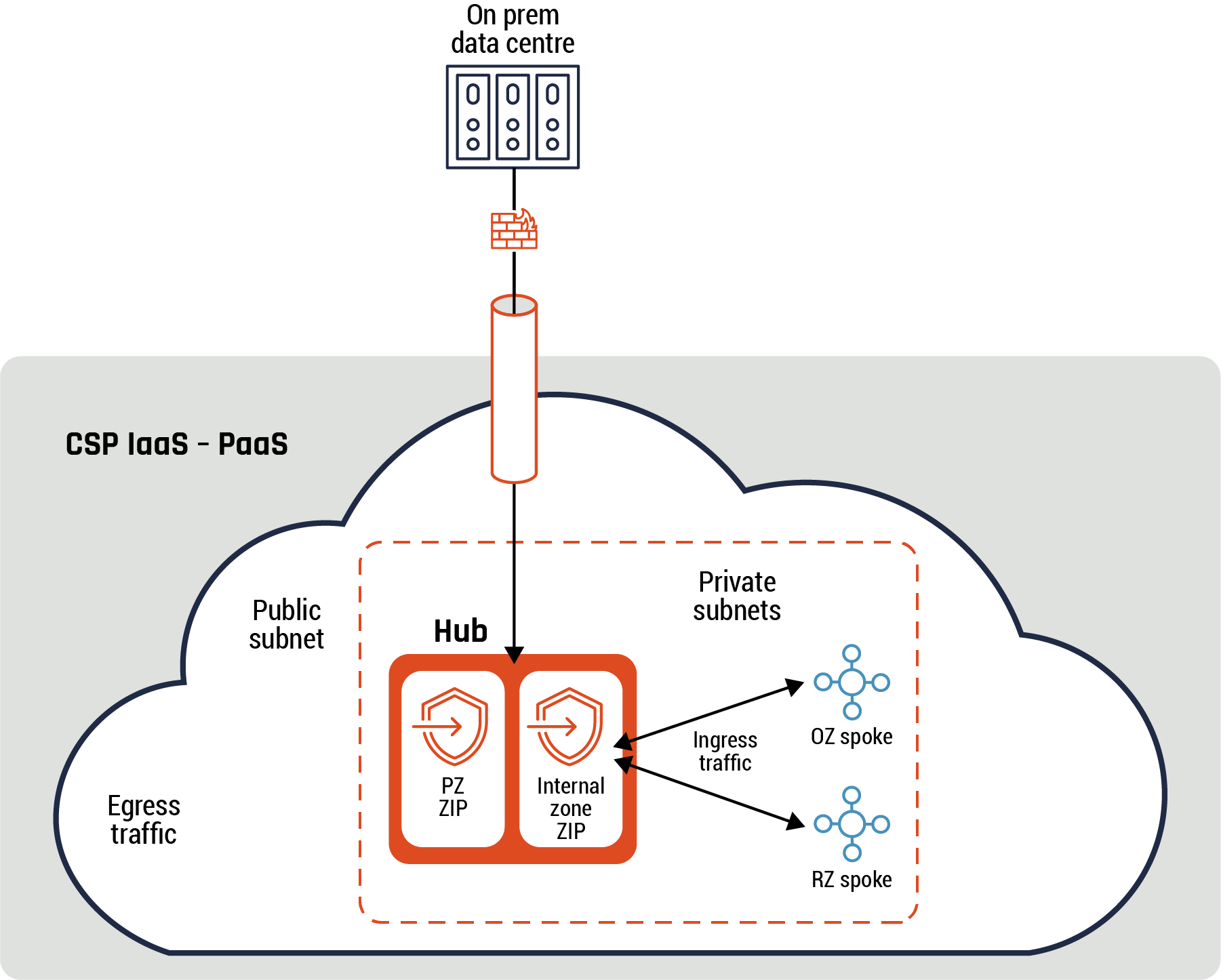
Figure 4: Hub and spoke connectivity pattern
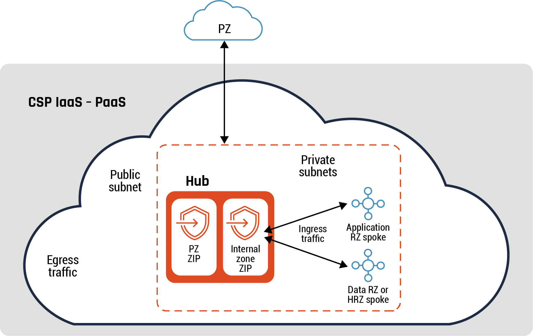
Long description - Hub and spoke connectivity pattern
Figure 4 demonstrates the hub and spoke pattern. It is a diagram with a large cloud icon and one small cloud icon marked with “PZ”. This smaller cloud represents the public zone and shows an arrow running from the PZ to the internal CSP IaaS or PaaS cloud environment. There is a rectangle shape outlined with a dashed line and within it are two additional rectangles marked “PZ ZIP” and “Internal zone ZIP” under the word Hub. Both the PZ ZIP and the Internal zone ZIP connected ingress traffic within private subnets to the application RZ spoke and the Data RZ or HRZ spoke. One the left-hand side of the large cloud icon are the words “public subnet” and “egress traffic.”
Note: The private interface of the internal zone ZIP and the ZIP private subnet can be the same for egress and ingress traffic flows or can be different private interfaces and private subnets. In addition, this pattern applies to all diagrams in the rest of this document that depicts ingress or egress traffic flows.
There is logical separation between egress and ingress traffic flows based on the above diagram. Therefore, the hub serves a dual function without having to split it into two and has both a private subnet and a public subnet. The spokes are hosted on private subnets.
Guidance
The hub PZ ZIP should be used to filter packets based on your organization’s defined characteristics and should present only those services needed to communicate with the PZ. The hub internal zone ZIP(s) can act as a ZIP for the spokes if it meets all the security functions and requirements outlined in Annex A. For instance, your organization can deploy a cloud-native firewall, third-party NGFW appliance, or a load balancer within the hub together with UTM for egress traffic between the PZ and the hub.
For ingress traffic, the hub can act as a ZIP if the spokes don’t have an integrated ZIP within their spoke. If each spoke has an integrated ZIP, then the hub can provide network routing capabilities including access control. In this instance, all the resources within the hub have the same data classification and are managed together.
Refer to the hybrid pattern and intermediary pattern for additional information on how these patterns can be integrated.
Below are three use cases specific to the ingress traffic in a hub and spoke pattern based on your organization’s security policy and risk management framework:
- The spokes within the same hub can communicate with each through the hub ZIP, together with other finer-grained access controls, which can be used to restrict traffic flows as required. For instance, an internal user has access to a web portal which retrieves data about a customer from different sources. The customer has both personal and business accounts, and the application’s data are accessible using different interfaces on different spokes. The apps have direct connectivity with each other for updates, like customer name changes. Refer to Annex D, Figure 20: Example of API gateway, API services, and containers for more details.
- There is no direct connectivity between the spokes based on your organization’s security requirements. All traffic between the spokes is through the hub. For instance, the spokes host workloads for your organization’s test, development, pre-production, and production environments. Refer to Annex C, Figure 17: An example of hub and spoke pattern for more details.
- There is both direct connectivity and no direct connectivity between some spokes based on your organization security requirements. For instance, one of the spokes hosts your organization operations zone while the other spokes host workloads for test, development, pre-production, and production environments. The production and pre-production environments have similar hardware and software configurations except for the former is fully redundant (all components are deployed in pairs). The OZ has direct connectivity to all four environments and hosts virtual desktops. However, there is no direct connectivity between the four environments.
For instance, a support ticket is submitted for a bug encountered by a user in the production environment and is assigned to a developer. The developer will confirm the bug by using a virtual desktop in the OZ to access the production environment. Then, the developer will use the pre-production environment to debug the ticket by launching a user session from OZ. Refer to Annex C, Figure 19: Third example of hub and spoke pattern for more details.
6.3 Hybrid pattern
Highlights of this pattern
The hybrid pattern is a networking design model for efficiently managing security requirements and communication between a cloud hub and on-prem data centre workloads and users. Systems, for example APIs, and users can access required services either on your organization’s on-prem network or within your cloud environment.
The hybrid pattern provides the following benefits to your organization:
- Network: Allows for network connectivity between your organization’s on-prem data centre and cloud environment
- Compliance: Your network traffic will traverse across a dedicated private network
- Scalability: Additional dedicated bandwidth can be provisioned in collaboration with your CSP and a telecommunication cloud exchange provider intermediary
Figure 5: Hybrid connectivity pattern
Long description - Hybrid connectivity pattern
Figure 5 is a diagram depicting the hybrid connectivity pattern. There is an icon with three pillars at the top of the diagram which represents the on-premises data centre. The data flows from the on-prem data centre, through a firewall icon and a tube icon representing a secure connection or channel that enters an image of a cloud to represent the CSPs IaaS or PaaS environment. Within the large cloud icon is a rectangle with dashed lines that consists of two additional rectangles with a security badge and arrow to represent the PZ ZIP and the Internal zone ZIP. Both of these ZIPS connect ingress traffic to the QZ or RZ spoke. Outside of the rectangle with dashed lines, but still within the cloud icon, are the words public subnet and egress traffic.
In the above diagram, there is direct connectivity between your organization’s on-prem data centre and cloud environment.
All traffic between your organization’s on-prem data centre and cloud environment have to go through the ZIP. In addition, the ZIP includes a reverse proxy that is used to mediate and inspect all traffic between the PZ and your workloads (hosted on your on-prem data centre and cloud environment). Depending on your organization’s security policy, traffic from the PZ can be restricted to only access workloads in your cloud environment.
Guidance
The hub can act as a ZIP if it meets all the security functions and requirements outlined in Annex A. For instance, you can deploy cloud-native firewall or third-party NGFW appliances in the hub with UTM for egress network traffic between the hub and the on-prem data centre. In addition, the spoke account has implemented a ZIP then the hub can provide network routing capabilities including access control.
Traffic between the on-prem network and the hub should be protected using IPsec configured according to ITSP.40.062Footnote 10 or MACsec configured with cryptographic algorithms from ITSP.40.111Footnote 11. As the data sensitivity increases, there may be a need to leverage additional capabilities such as, but not limited to, VPN dual tunnels and the use of dedicated links from the same vendor or different vendors. VPN dual tunnels are used to encrypt data which provides enhanced protection and redundancy.
6.4 Intermediary pattern
Highlights of this pattern
The intermediary pattern is a networking design model for efficiently managing security requirements and communication between a hub and a PZ such as the Internet or the hub and your organization’s data centre.
The intermediary pattern can be implemented by your organization or a third-party provider. The implementation can be within the CSP virtual environment or can be deployed on-prem or at the Cloud Exchange Provider (CXP) as part of the CSP private dedicated network connectivity.
The intermediary pattern provides the following benefits:
- Network: All network traffic to and from the PZ must go through the intermediary, which enhances the management of network connectivity with PZ.
- Compliance:
- Network traffic traverses a dedicated ZIP that meets all the security functions and requirements of a ZIP. The hub may lack some ZIP features and those are augmented by the intermediary. For instance, common services which are consumed by the spokes, such as NGFW, IDS and DNS, are hosted by the hub. Services which must be isolated based on security requirements, such as monitoring and compliance services, are hosted by the intermediary.
- In a government-wide or large private sector with multiple LOBs all traffic from the various LOBs is mediated by the intermediary. In this use case, the intermediary acts as a central hub for all the other LOB hubs.
- Scalability: Additional dedicated bandwidth can be provisioned in collaboration with the CSP and a telecommunication cloud exchange provider intermediary.
Figure 6: Intermediary connectivity pattern
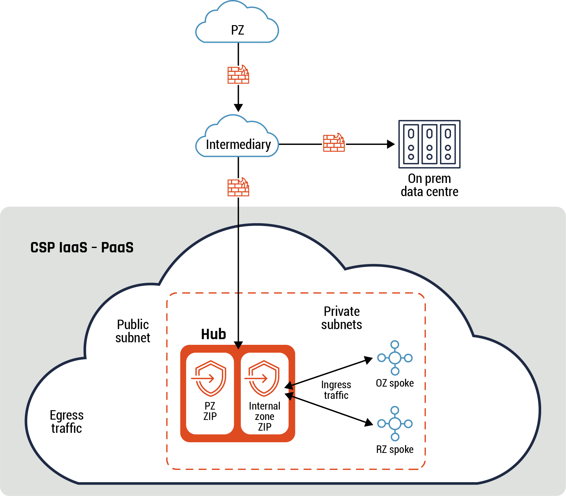
Long description - Intermediary connectivity pattern
Figure 6 highlights how an intermediary connectivity pattern works. Data and traffic flow from the PZ cloud icon at the top of the diagram, through a firewall to the intermediary cloud icon. From there, the traffic and data can flow to through a firewall to the on prem data centre represented by an icon with three pillars, or through a separate firewall to the CSP’s environment (represented by a large cloud icon). Within the cloud icon, there is a rectangle outlined in a dashed line. Inside this rectangle is the CSP’s HUB, which includes the PZ ZIP and the Internal zone ZIP, represented by two rectangles with security badges and arrows. The ingress traffic flows from the PZ ZIP or the Internal zone ZIP to the OZ or RZ spoke within the private subnets. On the left-hand side of the rectangle with the dashed lines are the words “public subnet” and “egress traffic.”
Guidance
The intermediary provides the capabilities of a ZIP, if it meets all the security functions and requirements outlined in Annex A. For instance, you can deploy a cloud-native firewall or third-party NGFW appliance within the intermediary with UTM for egress traffic between the intermediary and the hub.
A common use case for this pattern is an organization that sends all its traffic to the cloud environment through a CASB, which acts as an intermediary, to centralize configuration. The organization uses the CASB to consolidate all access to its cloud environment.
6.5 Data enclave pattern
Highlights of this pattern
Data security, especially data exfiltration, is one of the primary concerns for organizations. Data security is best addressed via a multi-layer defence-in-depth that incorporates security strategy, governance, IAM, application security, and incident response management. The data enclave pattern is part of the application security layer to be used in instances of the RZ or HRZ.
A data RZ or data HRZ enclave pattern provides the following benefits to your organization:
- Perimeter Security:
- Allows for fine-grained perimeter controls. You can mitigate exfiltration risks by isolating multi-tenant services, which prevents data from being copied to unauthorized resources outside the perimeter.
- Security perimeter: You can control which CSP services are accessible from a virtual network.
- Access control: Ensures your sensitive data can only be accessed from authorized virtual networks. This pattern provides an additional layer of security by denying access from unauthorized networks, even if the data is exposed by misconfigured IAM policies.
- Context-aware: You can restrict resource or user access to allowed IP addresses, identities, and trusted client devices.
Figure 7: Data enclave connectivity pattern
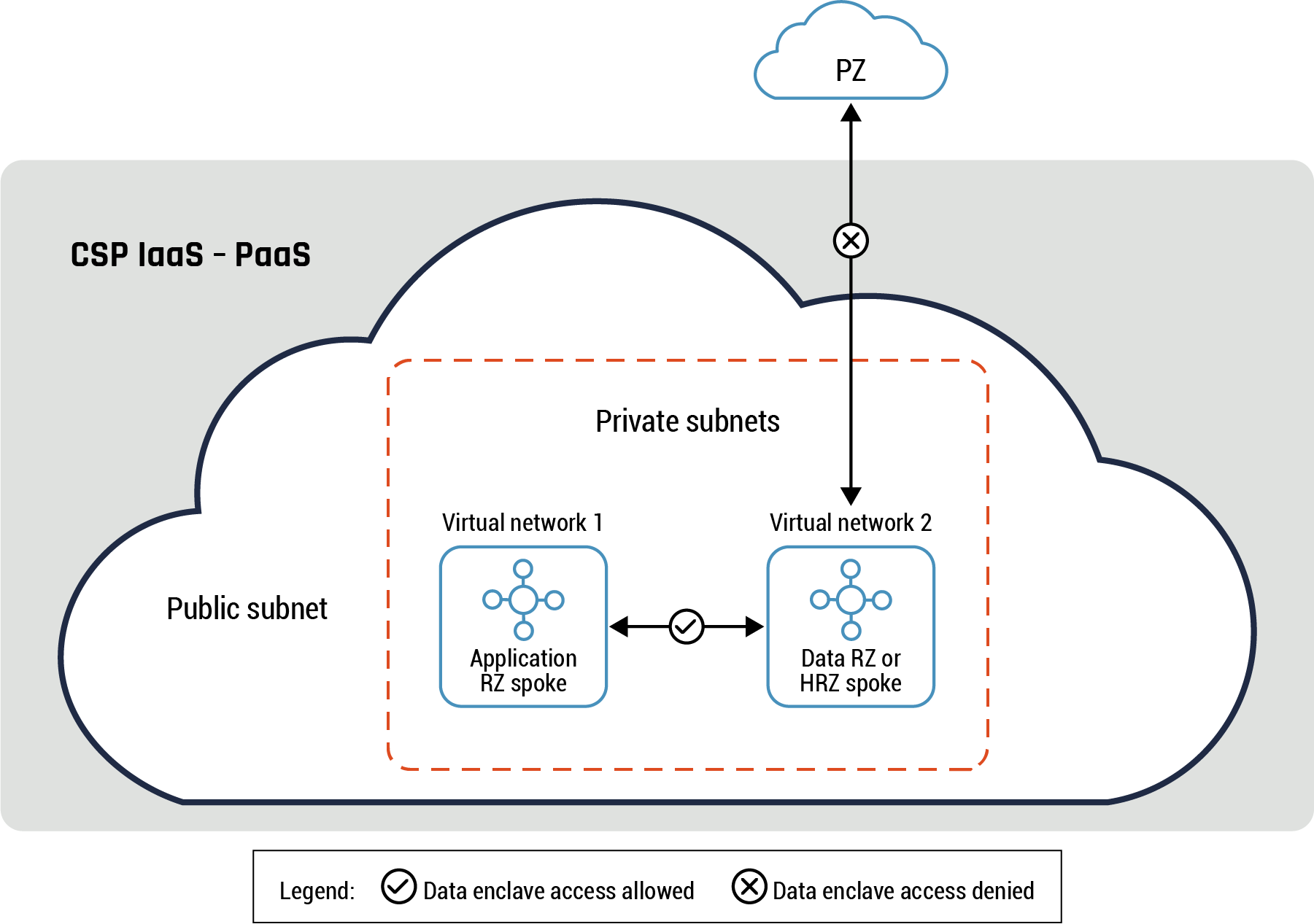
Long description - Data enclave connectivity pattern
Figure 7 is a diagram detailing the data enclave connectivity pattern. There is a small cloud icon at the top of the diagram to represent the PZ. Below the PZ cloud icon is a larger cloud image to represent the CSP’s Iaas-PaaS environment, containing the public subnet. There is a square with a dashed outline within the CSP’s cloud icon that contains two smaller squares. The first is labelled “Virtual network 1 – Application RZ spoke” and the second is labelled “Virtual network 2 – Data RZ or HRZ spoke.”
There is an arrow with a checkmark in the middle connecting virtual network 1 to virtual network 2. This represents the free flow of data and traffic between the two virtual networks. There is also an arrow connecting virtual network 2 to the PZ cloud icon. It has an ‘X’ in the centre to indicate that traffic may not flow between the data RZ or HRZ spoke and the PZ.
In the above diagram, the two virtual networks can be part of different CSPs or on the same CSP with no direct connectivity between them except through the public subnet (virtual network #2). Direct connections to Data RZ or HRZ subnet are not allowed except through the private subnet. This subnet hosts restricted cloud service APIs. Also, the data RZ or HRZ subnet doesn’t initiate or respond to service requests directly except through the private subnet.
Guidance
A data enclave should be implemented within a virtual network or in a container environment for data RZ or data HRZ. Refer to Annex C, Figure 18: Second example of hub and spoke pattern for more details.
While NACLs and NSGs provide a certain level of protection and should be leveraged using additional security capabilities such as context aware access, other, finer-grained access controls are required. A good example of these access controls required are restrictions on cloud service APIs. Refer to Annex C, Figure 18: Second example of hub and spoke pattern and Figure 19: Third example of hub and spoke pattern for more details on how NSGs can be used to restrict access between security zones within a spoke.
Refer to section 6.6 - Container patterns for additional information on how the data enclave can be integrated within those patterns.
6.6 Container patterns
We will outline two patterns in this section: sidecar and ambassador patterns.
Highlights of this pattern
These two container patterns benefit your organization by:
- enforcing container isolation
- restricting intra-container traffic flows in different zones within the cloud environment
- restricting inter-container traffic flows between the cloud environment and on-prem network and or PZ.
6.6.1 Sidecar pattern
The sidecar pattern consists of two containers to provide process isolation and segmentation: the helper and the primary container. The helper container abstracts the complexity of the primary container. The two containers are co-located on the same OS kernel and the helper shares the same fate as the primary container (e.g. on startup or shutdown). The helper consists of common functions such as logging, configuration, and file syncing. These functions are consumed by other containers.
This pattern can be used to handle data connectivity between the primary container and the other containers that are part of the microservice or other components of the solution. An example of this pattern usage is a web server (primary container) that provides content to external clients. The primary container requests the helper to retrieve the requested content from the backend database. The helper retrieves the requested content and provides it back to the web server. The server provides the retrieved content back to the external client. Refer to Figure 7 below for more details on the sidecar pattern.
The sidecar pattern is part of the data plane.
Figure 8: Sidecar pattern
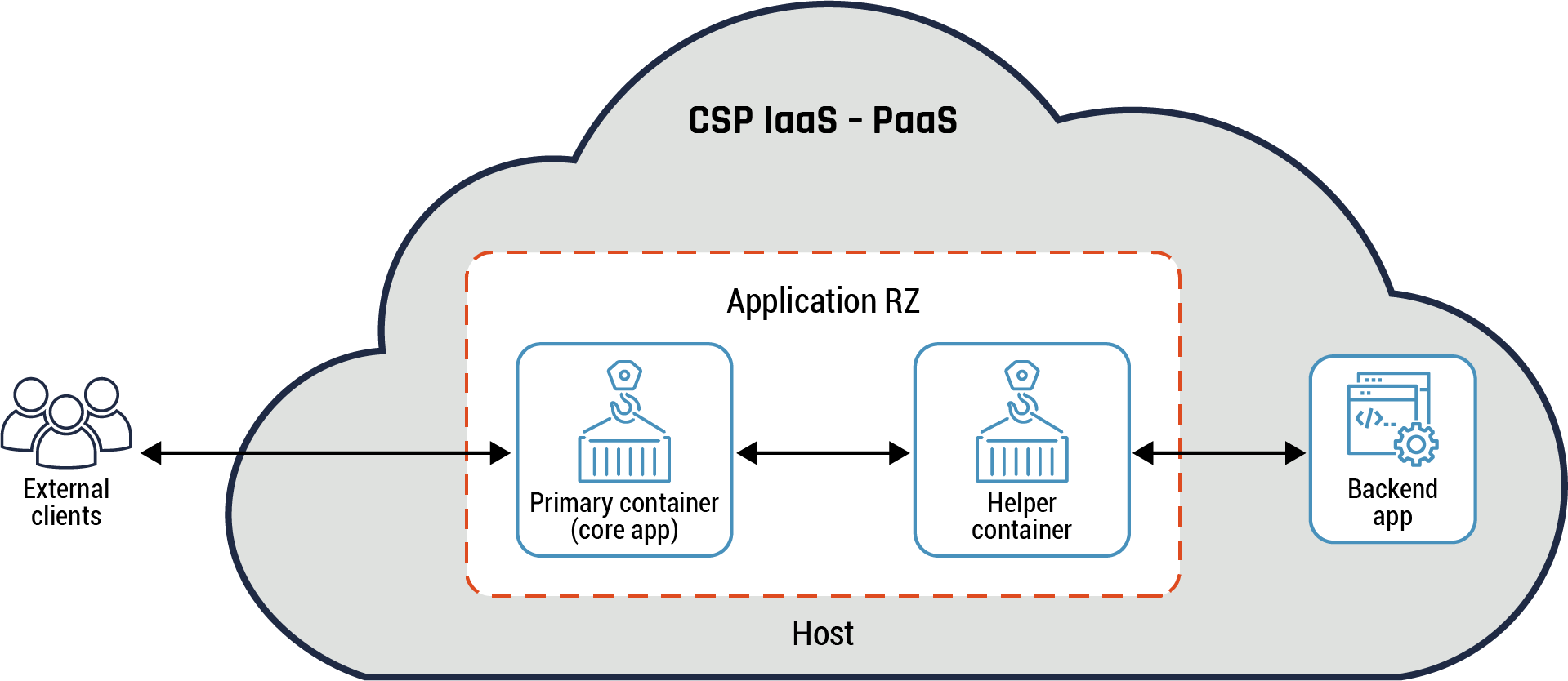
Long description - Data enclave connectivity pattern
Figure 8 is a diagram representing the sidecar pattern. It has one large cloud icon which represents the CSP’s IaaS-PaaS environment. External to the CSP’s environment is an icon of three people representing the external clients. An arrow connects them to the internal CSP environment, to a box representing the primary container (core app) within the host application RZ. There is another arrow connecting the primary container to another box representing the helper container. There is one last arrow connecting the helper container within the application RZ to a box labelled “backend app” to demonstrate the flow of data and traffic from an external client, through the application RZ to the backend app outside the host application RZ.
Guidance
The sidecar pattern can be implemented in a container environment for application RZ or data RZ. Process isolation is achieved as the helper handles both ingress and egress traffic flows for the primary container within the cloud environment. This pattern is typically implemented for each primary container and the helper communicates with other helpers. It’s normally managed using the container orchestrator which is part of the cloud control plane. Refer to section 6 and Annex D for more details on the container orchestrator and the cloud control plane.
6.6.2 Ambassador pattern
The ambassador pattern is used to handle data connectivity between the primary container and external components. This pattern consists of two containers that are co-located on the same OS kernel: a primary container and an ambassador. The ambassador acts as a proxy and provides a simplified view of the primary container. The ambassador assists the primary container with communication with other zones within the cloud environment and with the on-prem network or PZ. This pattern is part of the data plane.
The ambassador can be used to handle common client connectivity tasks such as monitoring, logging, routing, and database requests. Normally, this pattern is used to interface with legacy or end-of-life applications.
Figure 9: Ambassador pattern
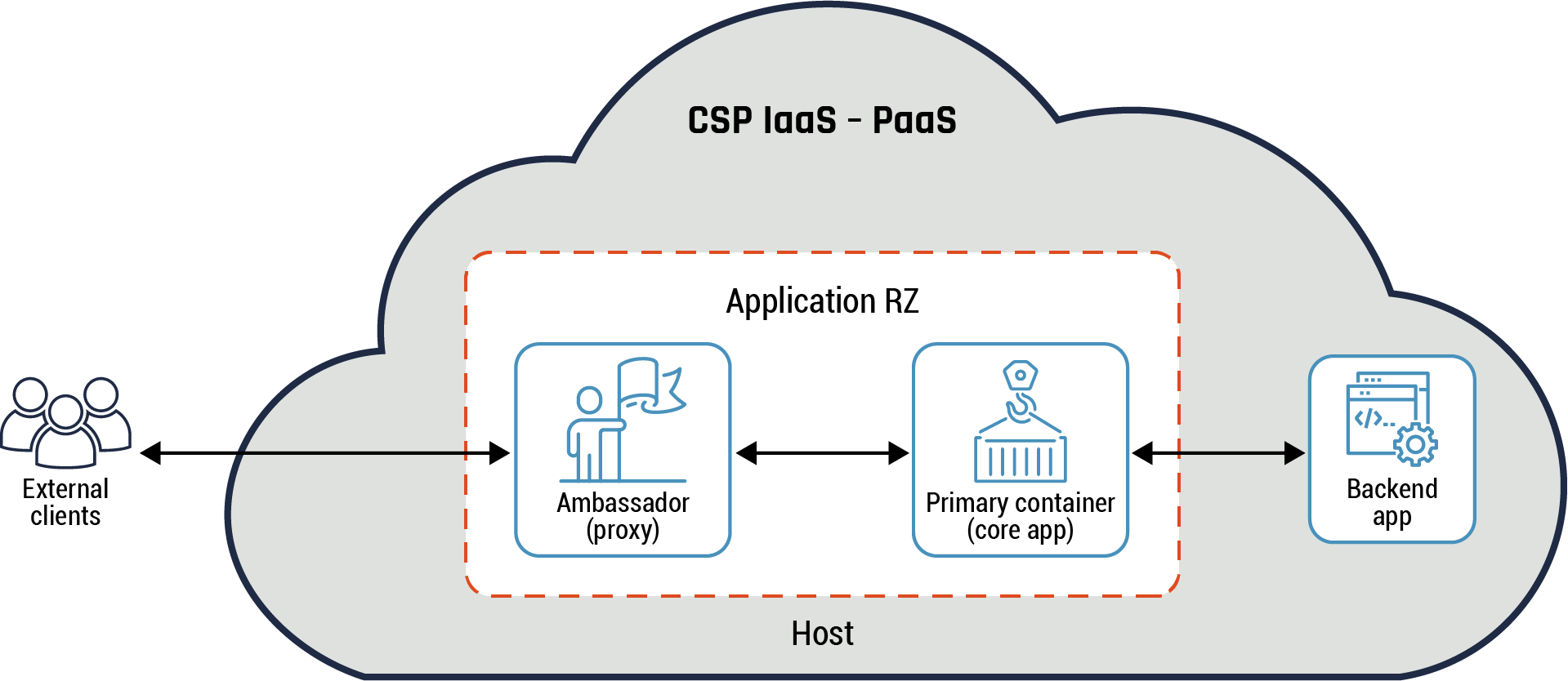
Long description - Ambassador pattern
Figure 9 provides an overview of the ambassador pattern. It has one large cloud icon which represents the CSP’s IaaS-PaaS environment. External to the CSP’s environment is an icon of three people representing the external clients. An arrow connects them to the internal CSP environment, to a box representing the ambassador (proxy) within the host application RZ. There is another arrow connecting the ambassador box to another box representing the primary container (core app). There is one last arrow connecting the helper container within the application RZ to a box labelled “backend app” to demonstrate the flow of data and traffic from an external client, through the application RZ to the backend app outside the host application RZ.
In the above diagram, the primary container is a web app, the ambassador handles all service requests from the primary container and acts as a database proxy to external databases.
Guidance
The ambassador pattern should be implemented in a container environment for application RZ or data RZ. Process isolation is achieved by having the proxy handle all the traffic flows for the primary container. This pattern is typically implemented when the primary container is required to be language-neutral, support legacy applications or support multiple applications and libraries. This pattern implementation may provide support for services that have large threat surfaces. In such instances, it’s recommended that appropriate mitigation measures should be used. Refer to section 4 - Cloud zoning guidance for more details on some of these mitigation measures that you can use.
6.7 Adapter pattern
Highlights of this pattern
The adapter pattern is used to present a standardized view of the application to the external entities. This pattern has two containers: primary and adapter. The primary container comprises the core application while the adapter handles all service requests between the primary container and external applications. The adapter handles common tasks such as retrieving metrics about the operational status of data plane components such as the primary container and formatting of data.
Refer to Figure 10 below for more details.
The adapter pattern provides the following benefits to your organization:
- Segmentation of external applications and application RZ or data RZ
- Primary container process isolation by restricting access
- Restrict egress traffic between the primary container and external applications
Figure 10: Adapter pattern
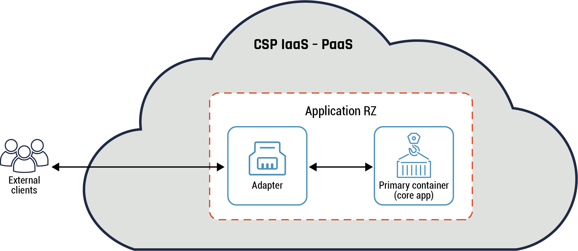
Long description - Adapter pattern
Figure 10 provides an overview of the adapter pattern. It has one large cloud icon which represents the CSP’s IaaS-PaaS environment. External to the CSP’s environment is an icon of three people representing the external clients. An arrow connects them to the internal CSP environment, to a box representing the adaptor within the host application RZ. There is another arrow connecting the adapter box to another box representing the primary container (core app).
Guidance
The adapter pattern should be implemented within a virtual network or in a container environment. It’s typically implemented when there is a requirement to connect two incompatible components such as the primary container and a third-party software. The adapter container provides an interface that both components can send requests to and receive a specific response.
In addition, the adapter container can be used to handle incompatible data formats.
For instance, the client sends a non-HTTP protocol request to the microservice which accepts HTTP v2 requests. The adapter will perform protocol conversion to allow communication between the client and the microservice. In such an instance, the adapter is acting as an API gateway connecting two dissimilar components or functions. Refer to section 6.9.1 - API pattern – API gateway for more details.
6.8 API pattern and API anti-pattern
We will consider two API patterns in this section: API pattern and API anti-pattern. In addition, we will consider two types of API patterns: the API endpoint and two different examples of the API gateway. These patterns provide functionality to enable a client to access a service and for the service to provide a response back. It should be noted that securing and monitoring of the APIs deployed is the responsibility of your organization.
Note: Refer to the TBS Application Modernization Guidance API First Architecture Patterns for Public Cloud P/IaaS (Word)Footnote 12 document for more details on API patterns and anti-patterns.
6.9 API pattern: API endpoint
Highlights of this pattern
A microservice must provide a disparate set of functions to different clients such as mobile devices and workstations. Some client requests require more functions and resources compared to other requests. This leads to additional overhead for the microservice. In addition, a client may need to make multiple requests before it retrieves all the required data.
The solution is to let an API endpoint (referred to as the API) handle all service requests between the different client types and the microservice (main application). This pattern, in its simplest form, involves placing an API between the client and the microservice. The API may have one or a few functions embedded within it. Refer to the API endpoint pattern diagram below for more details.
The API endpoint pattern provides the following benefits to your organization:
- Overhead in the microservice: The microservice lets the API handle all data connectivity with the client. The microservice provides its core functionality to the clients and offloads all non-core functions to the API.
- Process isolation: There is no direct access to the microservice except using the API. Therefore, it is isolated.
- Common services and the microservice business logic are decoupled. For instance, common services, such as authentication, authorization, and billing, are required for managing the interactions between the service and the client and are not part of the microservice business logic.
- Access control: The API can be used to enforce organizational security policies, such as authentication and authorization functions.
- Threat protection: Protection against attacks such as SQL injection, extensible markup language (XML) parser exploits and denial-of-service (DoS) attacks.
Figure 11: API pattern
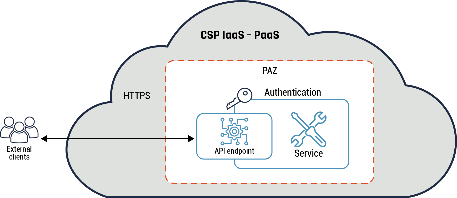
Long description - API pattern
Figure 11 demonstrates the API pattern in a diagram. There is a large cloud icon which represents the CSP’s IaaS-PaaS environment. External to the CSP’s environment is an icon of three people representing the external clients. An arrow connects them to the internal CSP environment, to a box with a gear icon inside, representing the API endpoint inside the PAZ. The API endpoint is within a larger box that represents the service within the PAZ. There is a key above the API endpoint icon and the word authentication, to demonstrate that the endpoint is protected and requires authentication before access to the service is permitted. External to the PAZ box, but still within the CSP IaaS-PaaS environment, there is text that reads HTTPS.
In the above diagram, the API endpoint can be used to expose functions for accessing and updating data accessible to the client service. This API is accessible from the PZ using HTTPS and provides identity services such as authentication.
Guidance
The API endpoint can be placed on the PAZ and used to perform edge functions for the microservice such as VPN gateway, routing, and monitoring. The API can be used in one-size-fits-all scenarios such as providing single functions. For instance, the API can be used to perform TLS decryption of a client request.
6.9.1 API pattern: API gateway
The API gateway is a more complex pattern compared to the API pattern. It can be used to handle use cases that require a diverse set of functions such as authorization, authentication, routing, monitoring, and billing. Like the API, the API gateway acts as a mediator between the client and the microservice. In addition, the API gateway can serve as a reverse proxy. Refer to Figure 11: API Pattern above for more details.
The API gateway solves similar problems as the API pattern. An API gateway also solves the following problems:
- Request and response transformation. For instance, the API gateway can modify the incoming request and add path parameters before forwarding the request to the microservice. In addition, the gateway can modify the response from the microservice before forwarding it to the client such as the gateway will modify the response and add a more generic error message instead of the detailed debugging error returned by the microservice.
- Traffic control. The API gateway can be used to manage the traffic to the microservice such as a load balancer.
We will consider two different implementations of the API gateway: monolithic and specialized. There are use cases that require different APIs to be deployed within the API gateway. For instance, an enterprise offers a PZ-facing application that is accessible using mobile devices, desktops, and API-driven applications (system-to-system connections). In such a scenario, it’s more efficient to use a specialized API that consists of three different APIs than using a monolithic API gateway.
Some of the problems the specialized API gateway solves:
- One-size-fits-all scenario of a monolithic API gateway: It’s more difficult to perform software maintenance on the monolithic API gateway because it has a lot of different functionality for the diverse set of services it provides. For instance, it’s much easier to update a single API within the specialized API than to update the monolithic API.
- API efficiency and performance: Each of the different APIs within the specialized API gateway provides specific functionality. In contrast, a monolithic API gateway isn’t optimized for efficiency and performance.
Figure 12: Monolithic API gateway pattern
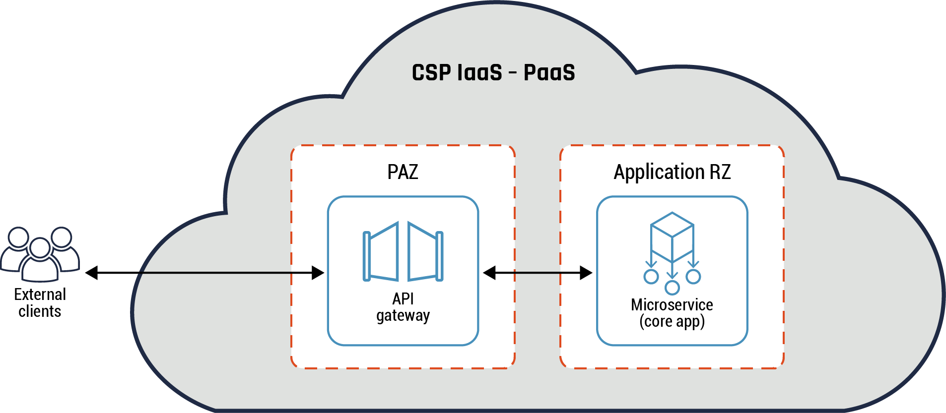
Long description - Monolithic API gateway pattern
Figure 12 provides an overview of the monolithic API gateway pattern. It has one large cloud icon which represents the CSP’s IaaS-PaaS environment. External to the CSP’s environment is an icon of three people representing the external clients. An arrow connects them to the internal CSP environment, to a box representing the API gateway inside the PAZ. There is another arrow connecting the PAZ and API gateway to another box representing the microservice (core app) inside the application RZ.
Figure 13: Specialized API gateway pattern
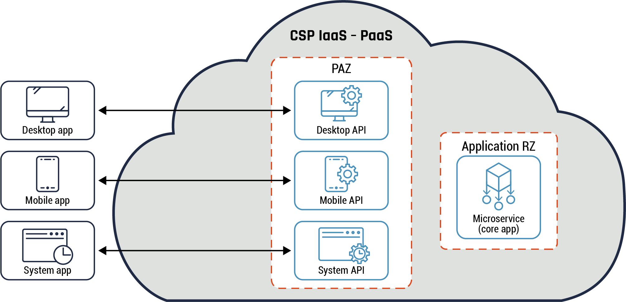
Long description - Specialized API gateway pattern
Figure 13 depicts the specialized API gateway pattern. It has one large cloud icon which represents the CSP’s IaaS-PaaS environment. External to the CSP’s environment are three boxes labelled: desktop app, mobile app, and system app. Each of these three boxes has an arrow connecting them to three separate boxes within the PAZ in the CSP’s environment. The desktop app box is connected to the desktop API box. The mobile app box is connected to the mobile API box. The system app box is connected to the system API box. To the right of the three boxes under the CSP’s PAZ is another box with a dashed line which represents the application RZ. Within the box is the microservice (core app).
Guidance
Like the API endpoint, both the monolithic and specialized API gateways can be placed on the PAZ and used to perform edge functions such as screening egress traffic flows for the microservice. For instance, the API gateway can be used to selectively exposes the microservices as APIs to the client applications, screen all incoming requests, and authenticate or authorize them.
In addition, the monolithic API gateway can be used to deploy a VPN functionality to provide secure connectivity between your on-prem data centre and your cloud environment among other services. The specialized API gateway can be used to handle use cases that require a diverse set of functions such as different types of users or nonperson entities (e.g. devices) that require access to the microservice.
6.9.2 API anti-pattern
Highlights of this pattern
Your organization may decide to use the API anti-pattern in limited cases that require more direct connectivity between the client and the microservice. An example of this pattern usage is the client-server architecture such as data connectivity between a client and a server application. Both components are deployed in a cloud environment. The server is deployed in the application RZ, while the client resides on a provisioned virtual desktop or endpoint (in the OZ). An API anti-pattern can be seen as a temporary solution to certain problems. For example, it can solve latency between the client and microservice due to its simple design which requires fewer components or devices being deployed. It also offers the benefit of allowing software components to be coupled together. It should be noted that, wherever possible, an API pattern should be used in place of the API anti-pattern. For more details, refer to Figure 14: API anti-pattern (example 1) and Figure 15: API anti-pattern (example 2) below.
Figure 14: API anti-pattern (example 1)
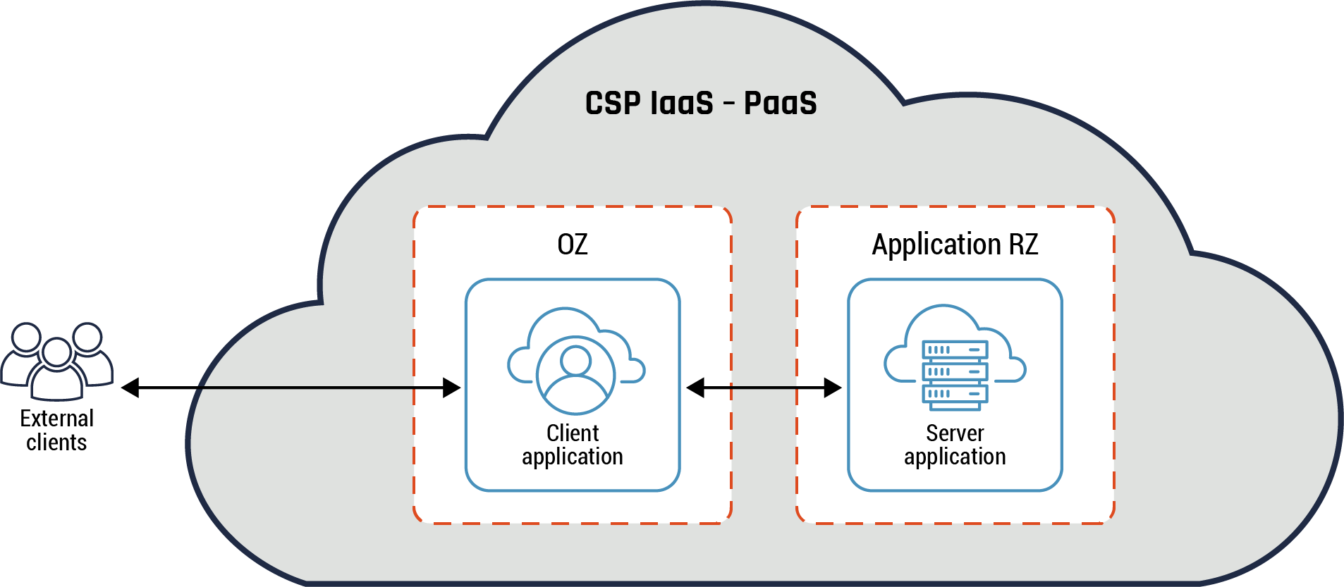
Long description - API anti-pattern (example 1)
Figure 14 demonstrates one example of the API anti-pattern. External to the CSP’s environment is an icon of three people representing the external clients. An arrow connects them to the internal CSP IaaS-PaaS environment, to a box representing the QZ, which contains the client application. There is another arrow connecting the QZ box to another box representing the application RZ, which contains the server application.
In the above example, there is direct connectivity between the client and the server (microservice). Data is aggregated in bulk and transferred using SCP. There are challenges with this deployment as an enterprise solution. We recommend an API-driven solution should be deployed to provide data in near real-time. For instance, common services such as authentication, authorization, and billing are often not standardized and need to be integrated into the individual services in these patterns.
Figure 15: API anti-pattern (example 2)
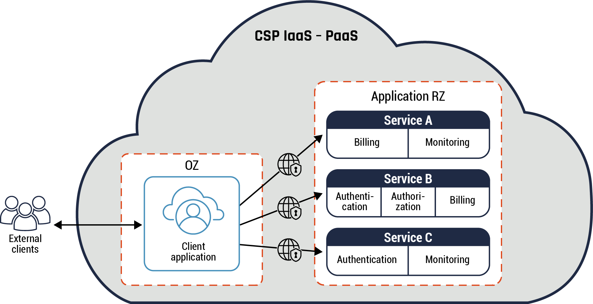
Long description - API anti-pattern (example 2)
Figure 15 demonstrates another example of the API anti-pattern. External to the CSP’s environment is an icon of three people representing the external clients. An arrow connects them to the internal CSP IaaS-PaaS environment, to a box representing the OZ, which contains the client application. There are three arrows pointing from the OZ client application box to three separate boxes. The first arrow connects the OZ client application to Service A, which contains billing and monitoring. The second arrow connects the OZ client application to Service B, which contains authentication, authorization, and billing. The third arrow connects the OZ client to Service C, which contains authentication and monitoring. All three of these arrows have an icon of a globe with a lock in the centre, representing a secure connection from the OZ to Service A, B, and C.
In the above example, the client communicates with each service individually. Each service may require common services, such as security and business services, to be integrated into it. In addition, the client may also be required to access the individual services using different unique resource locators (URLs).
Guidance
Both the client and the microservice are placed in different network zones. For example, the microservice is placed in data RZ and the client is in OZ.
NACLs and NSGs can be used to restrict access to the API anti-pattern components. Additional security capabilities such as context-aware and greater fine-grained access controls should be leveraged to provide more restrictions to the client and the microservice. Whenever possible, an appropriate API pattern should be used instead of the API anti-pattern.
7 Supporting content
7.1 List of abbreviations
- Term
- Definition
- API
- Application programming interface
- CASB
- Cloud Access Security Broker
- Cyber Centre
- Canadian Centre for Cyber Security
- CSE
- Communications Security Establishment
- CSP
- Cloud service provider
- CXP
- Cloud exchange provider
- DoS
- Denial of service
- DDoS
- Distributed denial of service
- DNS
- Domain name service
- FIPS
- Federal Information Processing Standards
- GC
- Government of Canada
- FTP
- File Transfer Protocol
- HTTP
- Hypertext Transfer Protocol
- HTTPS
- Hypertext Transfer Protocol Secure
- IaaS
- Infrastructure as a service
- IaC
- Infrastructure as code
- IDS
- Intrusion detection system
- IPsec
- Internet protocol security
- ISSIP
- Information System Security Implementation Process
- IT
- Information technology
- ITS
- Information technology security
- ITSG
- Information technology security guidance
- ITSP
- Information technology security guidance for practitioners
- MSSP
- Managed security service provider
- NACL
- Network access control list
- NGFW
- Next-generation firewall
- NIST
- National Institute of Standards and Technology
- NSG
- Network Security Group
- OSI
- Open Systems Interconnection (model)
- On-prem
- On-premises
- PaaS
- Platform as a service
- PAZ
- Public access zone
- PZ
- Public zone
- RBAC
- Role-based access control
- SaaS
- Software as a service
- SDN
- Software-defined network
- SQL
- Structured query language
- TBS
- Treasury Board of Canada Secretariat
- TLS
- Transport layer security
- UTM
- Unified threat management
- VM
- Virtual machine
- VPN
- Virtual private network
- WAF
- Web application firewall
- WAN
- Wide area network
- XML
- Extensible markup language
- ZIP
- Zone Interface Point
7.2 Glossary
- Term
- Definition
- Access Control
- Service to control access to authorized applications and services.
- Anti-pattern
- Any repeated (but ineffective) solution to a common problem
- Authentication
- The process of verifying an identity claimed by or for a system entity.
- Authorization
- Access privileges granted to a user, program, or process.
- Boundary
- A portion of the perimeter of a zone or network that is the point of connection between two zones or networks.
- Control plane
- Used to manage resources in a cloud environment using tools such as container orchestrator and SDN.
- Cloud access security brokers
- CASB are on-prem or cloud-based security policy enforcement points, placed between cloud service consumers and CSP to combine and interject enterprise security policies as the cloud-based resources are accessed. CASBs can be used to consolidate multiple types of security policy enforcement. Example of security policies enforced include authentication, single sign-on, authorization, credential mapping, device profiling, encryption, tokenization, logging, alerting, and malware detection/prevention.
- Cloud
- Cloud computing is a model for enabling anywhere, convenient, on-demand network access to a shared pool of configurable computing resources (e.g., networks, servers, storage, applications, and services) that can be rapidly provisioned and released with minimal management effort or service provider interaction
- Cloud fabric
- The servers, hghi-speed connections, and switches that make up a cloud computing infrastructure or framework.
- Cloud Service Provider
- A company that offers some component of cloud computing -- typically IaaS, SaaS or PaaS - to other businesses.
- Data plane
- Handles operational (user) traffic. This is where the resources managed by the control plane reside.
- Data path ZIP
- A ZIP that is deployed on the communication path between the zones that handles operational traffic (as opposed to management traffic). Operational traffic is associated with the user’s functionality.
- Data integrity verification
- The recipient can verify that the message received has not been modified while in transit and that it’s from the original sender.
- Data origin integrity
- The sender provides assurance that the message received has not been tampered with and that it was in a complete state prior to transmission.
- Denial-of-service (DoS) attack
- The prevention of authorized access to a system resource or the delaying of system operations and functions.
- Distributed denial-of-service (DDoS) Attack
- An attack in which multiple systems, usually compromised, are used to target a single system, causing a denial of service. Victims of a DDoS attack consist of both the end-targeted system and any systems maliciously used in the distributed attack.
- Dual tunnels
- Multiple encryption links, such as VPN tunnels, used for data going to the same destination using different interfaces. The tunnels are used to provide enhanced protection. The dedicated links would be from the same vendor or different vendors.
- End-to-end encryption
- Confidentiality service provided by encrypting data within, or at the source of, an end system with corresponding decryption occurring only within or at the destination end system.
- Firewall
- A gateway that enforces a boundary between two networks and that is used to isolate, filter, and protect local system resources from external connectivity by controlling the amount and the kinds of traffic that may pass between the two.
- Gateway
- An intermediate system that is the interface between two computer networks.
- GC Hybrid Connectivity Service
- This service provides secure connections between GC Enterprise data centres to CSPs over private connectivity links. It provides connectivity between on-prem users or applications and the cloud applications.
- Host
- A computer that is attached to a communication subnetwork and that can use network services to exchange data with other attached systems.
- Hub
- A virtual network that is centrally located between spokes for managing egress traffic and hosts common services used by the spokes. A hub can be used to manage ingress traffic depending on your organization security policy and / or risk management framework.
- Infrastructure as Code
- IaC is used to automate the configuration management of cloud environments and its resources. It ensures that the environment configuration is reproducible and traceable.
- Infrastructure as a Service
- The capability provided to the consumer is to provision processing, storage, networks, and other fundamental computing resources where the consumer can deploy and run arbitrary software, which can include operating systems and applications. The consumer does not manage or control the underlying cloud infrastructure but has control over operating systems, storage, and deployed applications; and possibly limited control of select networking components (e.g., host firewalls).
- Interface
- A boundary across which two systems communicate. An interface might be a hardware connector used to link to other devices, or it might be a convention used to allow communication between two software systems. Often, there is some intermediate component between the two systems that connects their interfaces together.
- Internal boundary system
- A gateway that connects two or more subnets within a network security zone.
- Internet
- The single, interconnected, worldwide system of commercial, governmental, educational, and other computer networks that share the set of protocols specified by the Internet Architecture Board (IAB) and the name and address spaces managed by the Internet Corporation for Assigned Names and Numbers (ICANN).
- Intrusion detection
- A security service that monitors and analyzes network or system events for the purpose of finding and providing real time, or near real-time, warning of attempts to access network or system resources in an unauthorized manner.
- Malware
- Short for malicious software. Software (e.g., logic bomb, trojan, virus, worm) that is intentionally included or inserted in a system for a harmful purpose.
- Microservice
- A set of containers that work together to form an application
- Managed Security Service Provider
- A MSSP provides outsourced monitoring and management of security devices and systems either from their own facilities or from other data centre providers. Common services provided include managed firewall, intrusion detection, VPN, vulnerability scanning and anti-viral services. MSSPs use high-availability security operation centres to provide 24/7 services designed to reduce the number of operational security personnel an enterprise needs to hire, train and retain to maintain an acceptable security posture.
- Management zone –connected ZIP (MZ-connected ZIP)
- A ZIP that is deployed on the communication path between the management zones and the communication path handles management traffic. MZ-connected ZIP is associated with system management functionality.
- Network security zone authority
- The person(s) responsible and accountable for the security of the network security zone.
- Network security zone
- A networking environment with a well-defined boundary, a network security zone authority, and a standard level of susceptibility to network threats. Types of zones are distinguished by security requirements for interfaces, traffic control, data protection, host configuration control, and network configuration control.
- Node
- An addressable device attached to a computer network. If the node is a computer, it’s more often called a host. The term node includes devices, such as routers and printers, that would normally not be called hosts.
- Perimeter
- An imaginary connecting line around a set of network components that defines the components contained in the zone.
- Public Access Zone
- A part of the network that is located between any two policy-enforcing components of the network (typically between the PZ and internal networks) and that enables an organization to host its own Internet services without risking unauthorized access to its private network.
- Platform as a Service
- The capability provided to the consumer to deploy onto the cloud infrastructure consumer-created or acquired applications created using programming languages, libraries, services, and tools supported by the provider. The consumer does not manage or control the underlying cloud infrastructure including network, servers, operating systems, or storage, but has control over the deployed applications and possibly configuration settings for the application-hosting environment.
- Protocol
- A set of rules (i.e. formats and procedures) to implement and control some type of association (e.g. communication) between systems. A series of ordered steps involving computing and communication that are performed by two or more system entities to achieve a joint objective.
- Proxy service
- An application-service networking function, which may be incorporated in a firewall, and which provides, to the client, replication of services available on other servers. To the client, the proxy appears to be the server, and to the server, it appears to be the client (when incorporated in a firewall, a proxy service is often referred to as an application gateway firewall.)
- Restricted extranet
- A highly constrained extension of an organization network, used to share information and resources with highly trusted, organizations. The restricted extranet may terminate in an organization-controlled zone (unlike the generic extranet which must terminate in the PAZ). Management and control of the interface should be mutually agreed upon by the two trusted parties involved.
- Secure virtual network (SVN)
- A virtual network (VN) that uses cryptography (e.g. IPsec) rather than a VPN based on logical isolation (e.g. multi-protocol label switching or Ethernet virtual local area networking).
- Security perimeter
- The boundary of the domain in which a security policy or security architecture applies (i.e. the boundary of the space in which security services protect system resources).
- Spoke
- This is a virtual network that host cloud workloads and connects to the hub through virtual network peering or networking gateway.
- Stateful inspection
- Packets are intercepted at the network layer for best performance (as in packet filters), but then data derived from all communication layers is accessed and analyzed for improved security (compared to layers 4-7 in application-layer gateways). Stateful inspection introduces a higher level of security by incorporating communication- and application-derived state and context information, which is stored and updated dynamically. This provides cumulative data against which subsequent communication attempts can be evaluated.
- Software as a Service
- The capability provided to the consumer is to use the provider’s applications running on a cloud infrastructure. The applications are accessible from various client devices through either a thin client interface such as a web browser (e.g., web-based email), or a program interface. The consumer does not manage or control the underlying cloud infrastructure including network, servers, operating systems, storage, or even individual application capabilities, with the possible exception of limited user-specific application configuration settings.
- Software Defined Network
- Software-defined networking is an approach to network management that enables dynamic, programmatically efficient network configuration to improve network performance and monitoring.
- Subnet
- Short for subnetwork. A portion of a network, which may be a physically independent network segment, that shares a network address with other portions of the network and is distinguished by a subnet number.
- Unified Threat Management
- A network firewall that has many features in one product, including email filtering, anti-malware capability, intrusion detection or prevention, and World Wide Web content filtering, along with the traditional activities of a firewall.
- Virtual Private Network
- Service used to establish private network connections between an external entity and your organization for authentication, authorization, and transmission confidentiality and integrity.
- Virtual Network (VN)
- A restricted-use, logical (i.e. artificial or simulated) computer network that is constructed from the system resources of a relatively public, physical (i.e. real) network (e.g. PZ), often by using encryption (located at hosts or gateways), and tunnelling links of the virtual network across the real network. In general terms, a VPN often refers to a network that emulates a private network, although it runs over public network lines and infrastructure.
- Vulnerability
- A weakness or gap in protection efforts of a network, a system, or an IT asset.
- Zone Interface Point
- An interface between two network security zones through which traffic may be routed.
Annex A Security requirements and cloud ZIP
The Cyber Centre’s ITSP.80.022 Baseline Requirements - Annex F: Zone Interface Point contains a set of objectives grouped by traffic control, network integrity and availability and data protection objectives. From these security objectives, a series of ZIP baseline security requirements are defined.
The following table contains a mapping of the ITSP.80.022 security objectives and security requirements to the cloud ZIP constructs previously defined. You should first refer and review the ITSP.80.022 document for the detailed requirement definition associated with the requirement number and the related ITSG-33 security control. It’s important for your organization to understand where best to leverage a particular ZIP based on the security requirements of what is being protected and the organizational security policy.
Table 3: Mapping of baseline requirement and cloud ZIP
Network interface
ZIP-NI-100
Maps to:
- Network access control list
- Network security group
- Next generation firewall
- Comments: All network paths must pass through a ZIP.
ZIP-NI-101
Maps to:
- Network access control list
- Network security group
- Next generation firewall
- Comments: Limited number of ZIPs.
ZIP-NI-105
Maps to:
- Network access control list
- Network security group
- Next generation firewall
- Comments: Collection of data supported by network flow logs.
Traffic Control
ZIP-TC-101
Maps to:
- Network access control list
- Network security group
- Next generation firewall
- Comments: Separate management traffic from other network traffic (separation can be physical or logical).
ZIP-TC-102
Maps to:
- Network access control list
- Network security group
- Next generation firewall
- Comments: In an emergency or increase threat can respond quickly to heightened security levels.
ZIP-TC-103
Maps to:
- Network access control list
- Network security group
- Next generation firewall
- Comments: In a traditional data centre, a ZIP can be used to provide authentication between two network zones and communications between services in those zones.
- A ZIP is used to provide connection authorization at the transport layer (Open Systems Interconnection model layer 4) between two network zones in a cloud environment and communications between services in those zones. Some CSPs are beginning to offer this capability.
ZIP-TC-105
Maps to:
- Network access control list
- Network security group
- Next generation firewall
- Comments: Principal of least privilege for traffic.
ZIP-TC-106
Maps to:
- Network access control list
- Network security group
- Next generation firewall
- Comments: 1 class of service is provided.
ZIP-TC-107
Maps to:
- Network access control list
- Network security group
- Next generation firewall
- Comments: Addressing model that detects and can diagnose malicious traffic.
ZIP-TC-110
Maps to:
- Network access control list
- Network security group
- Next generation firewall
- Comments: Principal of least privilege for access control.
ZIP-TC-111
Maps to:
- Network security group
- Next generation firewall
Does not map to:
- Network access control list
- Comments: NACL are stateless.
ZIP-TC-112
Maps to:
- Next generation firewall
Does not map to:
- Network access control list
- Network security group
- Comments: NACL/NSG supported by network flow logs. Alerting enabled by other cloud services.
ZIP-TC-113
Maps to:
- Next generation firewall
Does not map to:
- Network access control list
- Network security group
- Comments: NACL/NSG PZ content filter is not available.
ZIP-TC-120
Maps to:
- Network access control list: N/A
- Network security group: N/A
- Next generation firewall: N/A
- Comments: SLA with service provider for common infrastructure.
ZIP-TC-122
Maps to:
- Network access control list
- Network security group
- Next generation firewall
- Comments: Reject malformed traffic.
ZIP-TC-123
Maps to:
- Network access control list
- Network security group
- Next generation firewall
- Comments: NACL/NSG operate at OSI layer 3 and 4. NGFW can operate at OSI layer 3 and above.
ZIP-TC-124
Maps to:
- Network access control list
- Network security group
- Next generation firewall
- Comments: Traffic filtering capability between PZ and PAZ.
ZIP-TC-125
Maps to:
- Network access control list
- Network security group
- Next generation firewall
- Comments: Principal of least privilege for source and destination addresses.
Network Configuration
ZIP-NC-100
Maps to:
- Network access control list
- Network security group
- Next generation firewall
- Comments: NACL/NSG supported by cloud audit logs.
ZIP-NC-103
Maps to:
- Network access control list
- Network security group
- Next generation firewall
- Comments: Network topology can be periodically verified. For instance, infrastructure as code can be used to verify that the network topology of the cloud environment conforms to the baseline configuration.
ZIP-NC-104
Maps to:
- Network access control list
- Network security group
- Next generation firewall
- Comments: Network configuration can be assessed for unauthorized connections.
ZIP-NC-105
Maps to:
- Network access control list
- Network security group
- Next generation firewall
- Comments: NACL/NSG supported by RBAC and Policy. Control plane access is protected by and integrated with these features.
ZIP-NC-109
Maps to:
- Network access control list
- Network security group
- Next generation firewall
- Comments: Only authenticated and authorized administrators can manage ZIP nodes.
ZIP-NC-110
Maps to:
- Network access control list
- Network security group
- Next generation firewall
- Comments: Changes can be approved before being implemented.
Host Configuration
ZIP-HC-100
Does not map to:
- Network access control list
- Network security group
- Next generation firewall
- Comments: Host configuration is out of scope in this cloud zoning publication.
ZIP-HC-101
Does not map to:
- Network access control list
- Network security group
- Next generation firewall
- Comments: Host configuration is out of scope in this cloud zoning publication.
ZIP-HC-103
Does not map to:
- Network access control list
- Network security group
- Next generation firewall
- Comments: Host configuration is out of scope in this cloud zoning publication.
ZIP-HC-104
Does not map to:
- Network access control list
- Network security group
- Next generation firewall
- Comments: Host configuration is out of scope in this cloud zoning publication.
ZIP-HC-105
Does not map to:
- Network access control list
- Network security group
- Next generation firewall
- Comments: Host configuration is out of scope in this cloud zoning publication.
ZIP-HC-106
Does not map to:
- Network access control list
- Network security group
- Next generation firewall
- Comments: Host configuration is out of scope in this cloud zoning publication.
ZIP-HC-111
Does not map to:
- Network access control list
- Network security group
- Next generation firewall
- Comments: Host configuration is out of scope in this cloud zoning publication.
ZIP-HC-112
Does not map to:
- Network access control list
- Network security group
- Next generation firewall
- Comments: Host configuration is out of scope in this cloud zoning publication.
Data Protection
ZIP-DP-101
Maps to:
- Network access control list
- Network security group
- Next generation firewall
- Comments: A ZIP can support encrypted data traffic connections between zones. Refer to the Cyber Centres Guidance on Cloud Service Cryptography (ITSP.50.106) for more details on encryption guidance applicable to the cloud.
ZIP-DP-103
Maps to:
- Network access control list
- Network security group
- Next generation firewall
- Comments: Data protection measures may be required depending on a ZIP security categorization and the results of the ISSIP. Data protection services may be applied at either the network layer or higher layers, depending on the implementation requirements. NACL/NSG operate at OSI layer 3 and 4 while NGFW can operate at OSI layer 3 and above.
ZIP-DP-104
Maps to:
- Next generation firewall
Does not map to:
- Network access control list
- Network security group
- Comments: NACL/NSG do not validate FIPS-140-2 encryption/digital signatures.
Annex B Accessing cloud workloads and use cases
In this section, we provide more details on some of the concepts that we covered in section 4 such as the hub and spoke pattern. In addition, we provide details on some common use cases specific to accessing cloud workloads which are hosted in CSP IaaS and CSP PaaS using the hub and spoke pattern.
The diagram below shows:
- an organization user accessing the on-prem network using VPN
- the organization user, system administrator and internal API accessing cloud workloads from the on-prem network
- the external user and external APIs accessing cloud workloads from the PZ
Also, the cloud workloads can access workloads on the on-prem network to complete the external user and API service requests. Refer to Table 4: Accessing cloud workloads and use cases for more details on the five use cases shown on the diagram.
Figure 16: Accessing cloud workloads and use cases
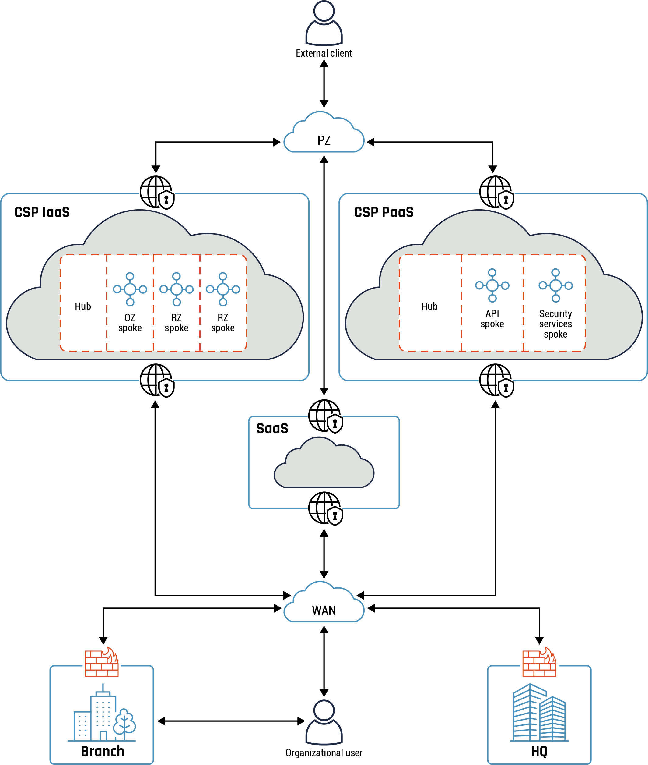
Long description - Accessing cloud workloads and use cases
Figure 16 demonstrates a common use case for accessing cloud workloads. At the top of the diagram is an icon of three people, representing the external clients. There is an arrow connecting them to a small cloud icon representing the PZ. From the PZ cloud, there are three separate arrows leading to three separate cloud environments.
The first arrow connects the PZ to the CSP’s IaaS environment which is outlined in blue with two world icons with locks indicating it is a secure zone with secure connections to the PZ. Within the CSP’s IaaS environment are four boxes with dashed line representing the hub, the OZ spoke, the RZ spoke, and another RZ spoke. There is a second arrow connecting the CSP’s IaaS to the WAN, which is represented by a small cloud icon, to show the traffic flow.
The second arrow connects the PZ to the CSP’s SaaS environment. It is represented as cloud icon inside a box. There is an arrow connecting the SaaS environment to the WAN. Both arrows have world icons with locks to represent the secure connections.
The third arrow connects the PZ to the CSP’s PaaS environment, which is represented by a cloud icon with three boxes inside. The three boxes represent the hub, the API spoke, and the security services spoke. There is an arrow connecting the SaaS environment to the WAN.
From the WAN, the traffic can flow two ways. The first is through a firewall to the branch, which is represented by an icon of a building. The second is through a firewall to the organization’s headquarters, which is representing by an icon with a skyscraper. Traffic will then flow from the branch to the organizational user, who is represented by an icon of a person.
The two CXP Dedicated Connections to CSP IaaS and CSP PaaS from the WAN can be from the same vendor or different vendors. The CASB can be used as a reverse proxy and to enforce your organization security policy such as authentication, authorization and single sign-on. In addition, it’s possible to use CXP Dedicated Connection to connect to either of the CSP (not shown on above diagram) based on your organization security policy.
Table 4: Accessing cloud workloads and use cases
- Reference
- Use case
- A1
- The organization user accesses the on-prem network using VPN from the PZ. The user, after being authenticated and authorized, can access IaaS and PaaS cloud workloads from the on-prem network. The same traffic flow applies to other users located on the on-prem network at the two branches and HQ in terms of accessing cloud workloads based on privileges granted by your organization. All traffic flows are secure.
- A2
- The system administrator accesses IaaS and PaaS cloud environments from on-prem network to perform management tasks.
- A3
- An external user accesses IaaS and PaaS cloud workloads from the PZ. Occasionally, the cloud workloads will access on-prem workloads hosted at either branch or HQ to fulfil service requests (depending on the cloud workloads business requirements and / or your organization security policy). This is shown using a light blue dotted line from IaaS and PaaS to WAN and then to HQ and the two branches.
- A4
- Internal API accesses cloud workloads from the on-prem network. The API is used to access organization services and data. All API traffic flows are secure.
- A5
- External API accesses cloud workloads from the PZ. The API is used to access organizational services and data. Occasionally, the cloud workloads will connect to on-prem workloads hosted at either branch or HQ to fulfil service requests (depending on the cloud workloads business requirements and / or your organization security policy). This is shown using a green dotted line from IaaS and PaaS to WAN and then to HQ and the two branches.
Annex C Examples of hub and spoke pattern
This section provides several examples of a hub and spoke pattern that you can implement in your organization cloud environment. These patterns are listed in order of increasing levels of complexity.
Below the hub and spoke pattern has two separate spokes hosting your test and development environments. There is no direct connectivity between the two spokes (environments) except through the hub. The hub hosts common services and has external connectivity to both your on-prem network and the PZ.
Figure 17: An example of hub and spoke pattern
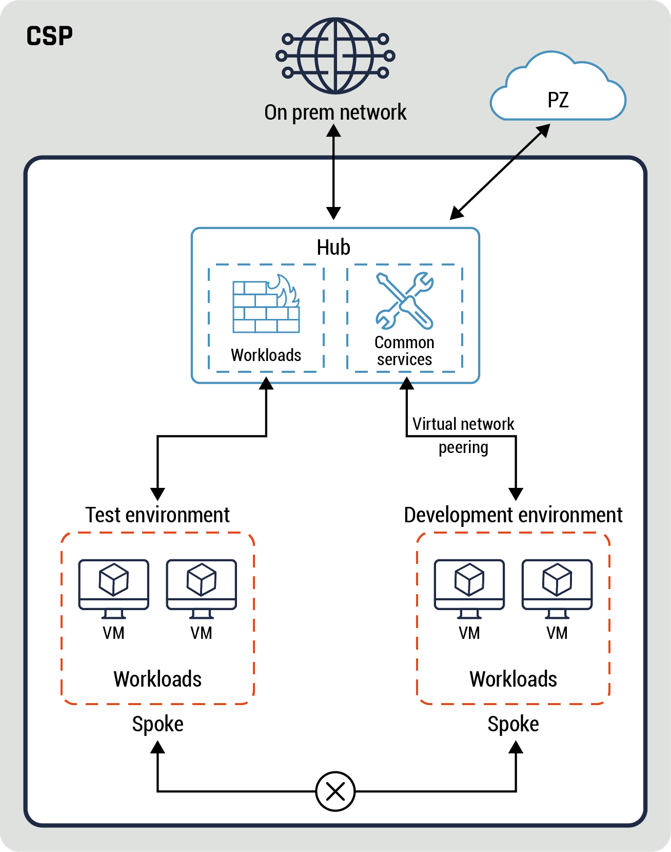
Long description - An example of hub and spoke pattern
Figure 17 highlights an example of the hub and spoke pattern. There is a large grey box with the words CSP at the top. This represents the CSP’s environment. At the top of the diagram, within the CSP’s environment, there is a world icon that represents the on-prem network. There is also a smaller cloud icon that represents the PZ. Both the on-prem and PZ icons have arrows connecting them to the internal CSP Hub, which is represented by a box. Inside the hub box are two icons representing the workloads and the common services. The workloads icon is connected by an arrow to a box with a dashed line representing the test environment. Within the test environment box are two icons representing two separate VMs, which represents the workloads. There is an arrow connecting the common services box, via virtual network peering, to the development environment, which is represented by a box with a dashed line. Within the development environment are two icons representing two separate VMs, which represents the workloads. Both the test environment and the development environment boxes are connected by an arrow with an X in the centre to represent the spoke.
Our next example is a hub and spoke pattern hosting both pre-production and production environments. The two environments are similar except for the former is fully redundant. An NSG is used to restrict access between the different security zones within each spoke. Similar to the previous example, there is no direct connectivity between the two spokes except through the hub. The hub provides external connectivity to the PZ and on-prem network based on your organization security requirements. Each spoke has a web, application, and database tiers.
In addition, there are restrictions on traffic flows between the three tiers using the NSG. The database tier is only accessible through the app tier while there is direct connectivity between the web and the app tiers. The database tier implementation is a solid example of the data enclave pattern.
Figure 18: Second example of hub and spoke pattern
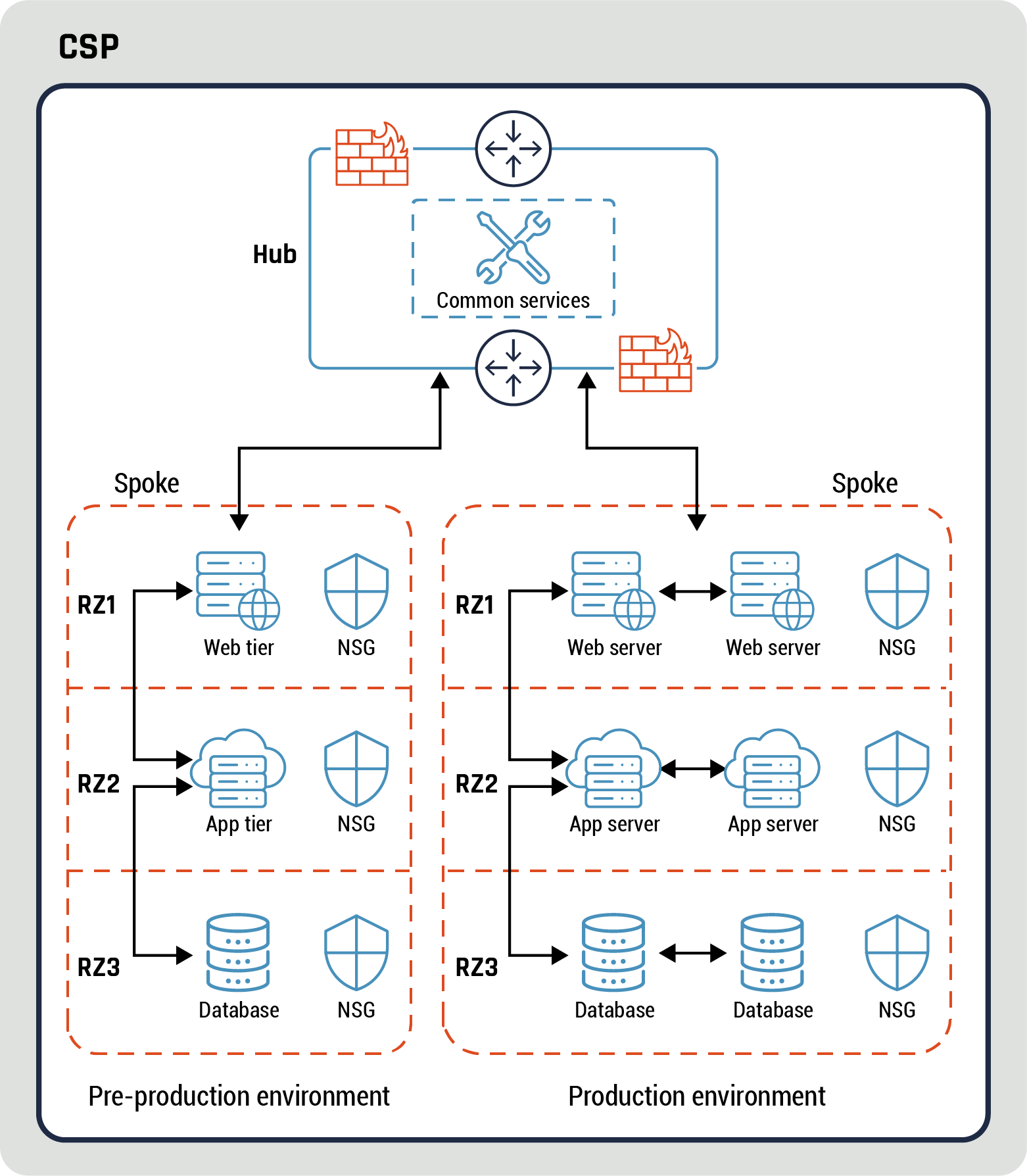
Long description - Second example of hub and spoke pattern
Figure 18 provides another example of the hub and spoke pattern. There is a large grey box with the words CSP at the top, which represents the CSP environment. Within the grey box is a second box containing the elements of the hub and spoke pattern. At the top of the diagram is a smaller box representing the hub. Within the hub are the common services, represented by an icon of tools. The hub and commons services are protected by a firewall, and the hub allows traffic to flow all ways through the firewall, as represented by an icon of four arrows pointing in each direction.
The hub is connected to two additional boxes with dashed lines, with the words “pre-production environment” under one box and the words “production environment” under the other box, representing two separate spokes.
The first spoke box contains three separate layers representing the RZ1, RZ2, and RZ3. In the RZ1 layer there is an icon of a server with a globe to represent the web tier and an icon of a security badge representing the NSG.
In the RZ2 layer, there is an icon of a server with a cloud behind it to represent the app tier, as well as an icon of a security badge representing the NSG. The web tier in RZ1 and the app tier in RZ2 are connected by an arrow.
In the RZ3 layer, there is an icon of a database and an icon of security badge representing the NSG. The app tier in RZ2 is connected to the database in RZ3 by an arrow.
The second spoke also has three layers, RZ1, RZ2, and RZ3. In the RZ1 layer, there are two icons of a server with a globe to represent the web servers, as well as an icon of a security badge representing the NSG.
In the RZ2 layer, there are two icons of a server with a cloud behind it to represent the app tiers, as well as an icon of a security badge representing the NSG. The web tiers in RZ1 and the app tiers in RZ2 are connected by an arrow.
In the RZ3 layer, there are two icons of databases and one icon of security badge representing the NSG. The app tiers in RZ2 are connected to the databases in RZ3 by an arrow.
Our next hub and spoke pattern has three spokes with operations zone, production and pre-production environments. This pattern is similar to the previous example except for the OZ which has direct connectivity to both environments. There is no direct connectivity between the two environments (pre-prod and prod). The OZ hosts virtual desktops which can be provisioned either dynamic (on-demand) or static based on your organization business requirements.
The hub provides external connectivity to the PZ and on-prem network based on your organization security requirements.
Figure 19: Third example of hub and spoke pattern
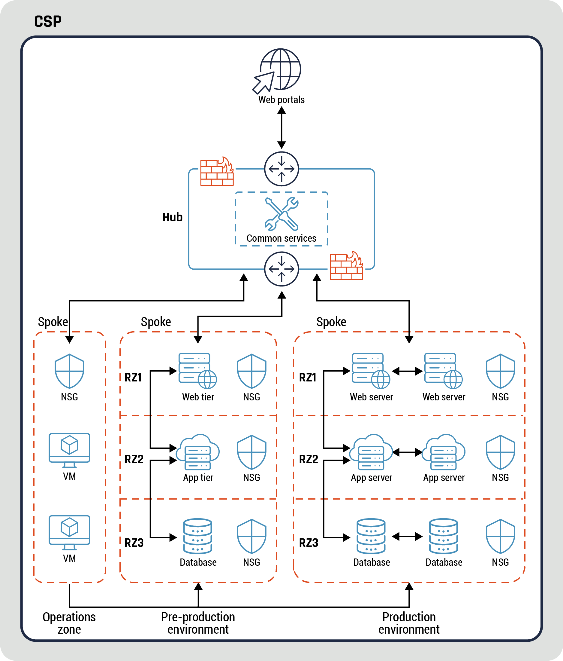
Long description - Third example of hub and spoke pattern
Figure 19 provides a third example of the hub and spoke pattern. There is a large grey box with the words CSP at the top, which represents the CSP environment. Within the grey box is a second box containing the elements of the hub and spoke pattern. At the top of the diagram is an icon of a globe with an arrow pointing to its centre, which represents web portals. There is an arrow connecting the web portal to the hub, which is represented by a box. Within the hub are the common services, represented by an icon of tools. The hub and commons services are protected by a firewall, and the hub allows traffic to flow all ways through the firewall, as represented by an icon of four arrows pointing in each direction.
The hub is connected to three additional boxes with dashed lines, with the words “operations zone” under the first box, “pre-production environment” under the second box, and the words “production environment” under the third box, representing three separate spokes.
The first spoke box contains three separate layers, each with an icon to represent a stage in the flow. The first icon in the first layer is a security badge that represents the NSG. The second icon in the second and third layers contain an icon of a computer screen with a cube in the centre to represent two separate VMs.
The second spoke box contains three separate layers representing the RZ1, RZ2, and RZ3. In the RZ1 layer there is an icon of a server with a globe to represent the web tier and an icon of a security badge representing the NSG.
In the RZ2 layer, there is an icon of a server with a cloud behind it to represent the app tier, as well as an icon of a security badge representing the NSG. The web tier in RZ1 and the app tier in RZ2 are connected by an arrow.
In the RZ3 layer, there is an icon of a database and an icon of security badge representing the NSG. The app tier in RZ2 is connected to the database in RZ3 by an arrow.
The third spoke also has three layers, RZ1, RZ2, and RZ3. In the RZ1 layer, there are two icons of a server with a globe to represent the web servers, as well as an icon of a security badge representing the NSG.
In the RZ2 layer, there are two icons of a server with a cloud behind it to represent the app tiers, as well as an icon of a security badge representing the NSG. The web tiers in RZ1 and the app tiers in RZ2 are connected by an arrow.
In the RZ3 layer, there are two icons of databases and one icon of security badge representing the NSG. The app tiers in RZ2 are connected to the databases in RZ3 by an arrow.
Annex D API gateway, API services and containers
The diagram in this section (Figure 20 below) shows an example of API gateway and different types of services deployed such as containers, apps, and API services. These services are deployed on two IaaS and PaaS private subnets. The services within IaaS and PaaS can communicate with each other. Also, there is connectivity between the IaaS and PaaS.
A firewall, such as a WAF, and API gateway are deployed on a hub which provides external connectivity to both the PZ and on-prem network. The WAF can be used to filter malicious traffic to the services on the two spokes. The API gateway acts as a reverse proxy and can be used to provide services such as authentication and authorization, among others.
Figure 20: Example of API gateway, API services, and containers
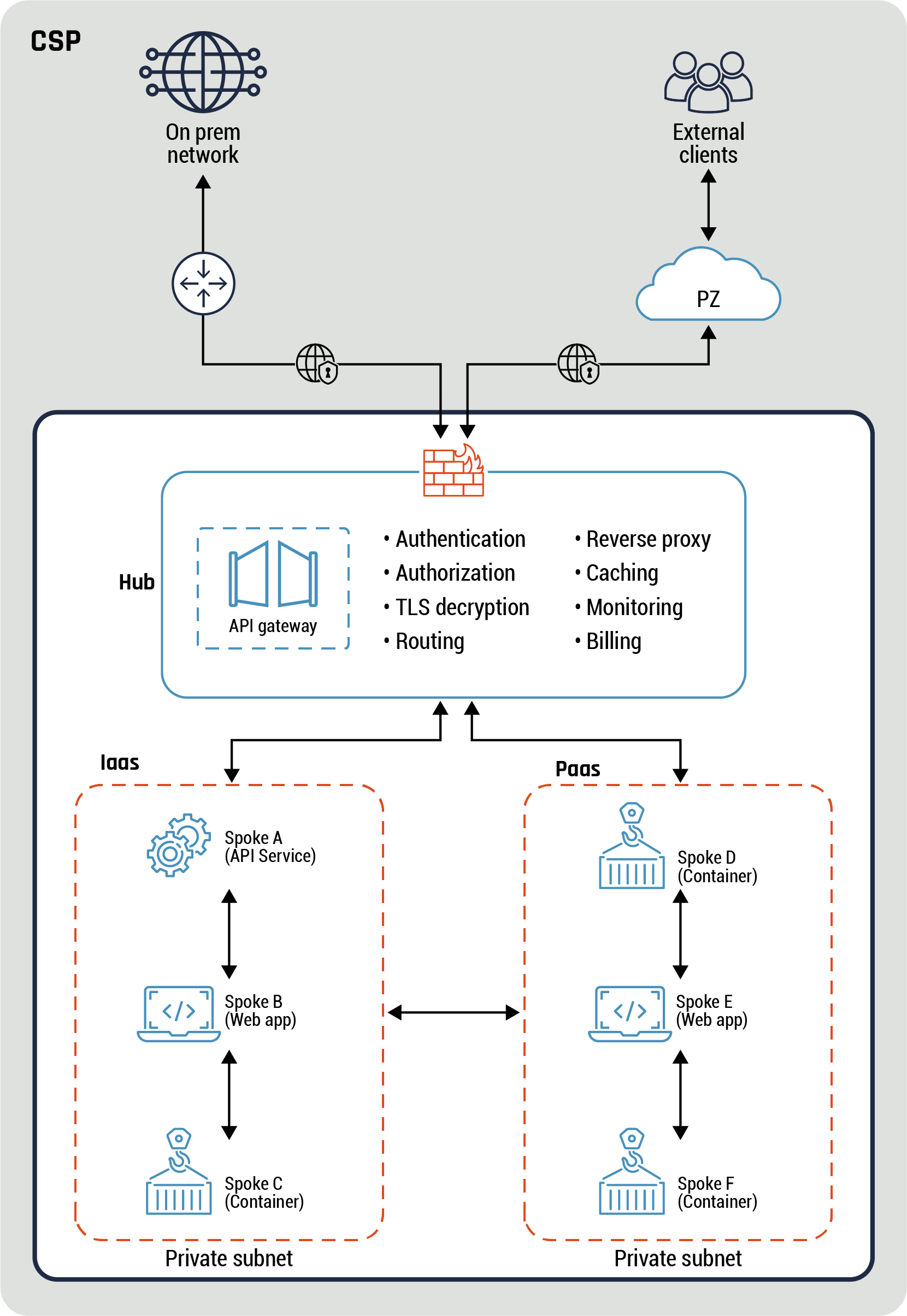
Long description - Example of API gateway, API services, and containers
Figure 20 provides an example of API gateways, API services, and containers. It demonstrates an example of an API gateway and the different types of services deployed. These services are deployed on two IaaS and PaaS private subnets.
The diagram has a large grey box with the word CSP to represent the CSP’s environment. At the top of the diagram there is an icon of a globe on the left-hand side representing the on-prem network. There is a line with arrows connecting the on-prem network to an icon of a globe with a lock to represent a secure connect. The line continues to connect to an icon of a brick wall with a flame representing a firewall. There is also an ion on the right-hand side of three people representing the external clients. There is a line with an arrow connecting the external clients to a cloud icon representing the PZ. There is another line connecting the PZ to a secure connection icon, finishing at the firewall icon.
Within the grey box is another large box to represent a zone. The firewall icon rests at the top of this box and connects to a smaller rectangle representing the hub. Within the hub is an icon of two gates representing the API gateway, as well as the following list of services:
- Authentication
- Authorization
- TLS decryption
- Routing
- Reverse proxy
- Caching
- Monitoring
- Billing
The hub box connects to two IaaS and PaaS private subnets, represented by two separate boxes. In the IaaS box there are three icons with arrows descending vertically. The first icon is of a gear and it represents spoke A (API service). It connects to the second icon of a laptop which represents spoke B (web app). The third icon is a sign on a hook representing spoke C (container).
In the PaaS box there are also three icons. With arrows descending vertically. The first icon is the same container icon used in the IaaS box and it represents spoke D. The second icon is a laptop to represent spoke E (web app). The third icon is the same icon for the two previous containers, and it represents spoke F.
There is an arrow connecting the IaaS and PaaS boxes to demonstrate connectivity between the two private subnets.
Below diagram depicts the difference between the placement of the control and data planes. As we stated before, the container orchestrator is part of the control plane. The two containers or apps are part of the data plane. All traffic flows between the control plane and the apps in the data plane are through the proxies. Traffic flows between the two apps are secured. In addition, all traffic flows between the control plane, data plane and the apps are secured.
Figure 21: Relationship between the control and data planes
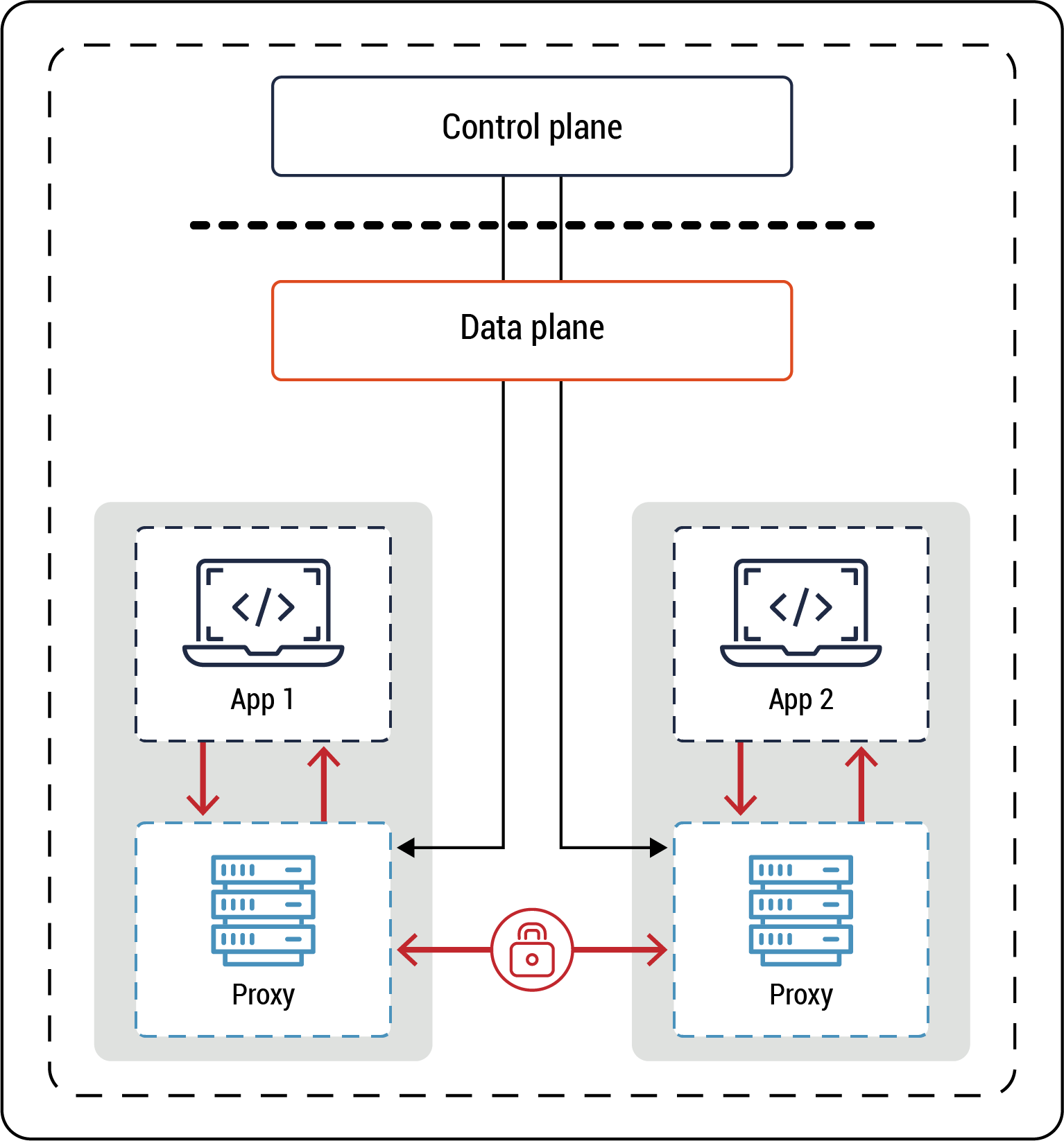
Long description - Relationship between the control and data planes
Figure 21 demonstrates the relationship between the control plane and the data plane. At the top of the diagram is a box representing the control plane. Underneath this box is a dashed line. Under the dashed line is a box representing the data plane. There are two lines with arrows that go from the control plane, across the dashed line, and into the data plane. One of these lines connects with a grey box on the left-hand side of the diagram, representing an application. The application contains an icon representing APP1 and another icon of a server representing its proxy. The second line connects with a similar grey box on the right-hand side of the diagram, representing another application. This grey box contains an icon representing APP2 and an icon of a server representing its proxy. There is a line with arrows at either end connecting both application proxies. The line has a lock in the middle indicating that all traffic flows between the two proxies in a secure manner. security, identity and access management, application security, monitoring and endpoint security.