
Optical fibre submarine telecommunications cables and the technologies and facilities that support them are critical infrastructure. Although they may be invisible to the average citizen, these systems are fundamental to global Internet and mobile connectivity. They are key conduits that connect people around the world and cross bodies of water at varying depths. Globally, they transmit most international telecommunications, meaning mobile, Internet and military communications. Our significant dependence on these systems is expected to increase in parallel to the exponential growth in telecommunications.
This publication provides insight into the threat landscape and outlines corresponding mitigation strategies to safeguard the integrity and reliability of cable infrastructure. It focuses primarily on commercial telecommunications networks and thus does not address in detail the risks introduced by or associated with strictly industrial, military, unsanctioned, or otherwise covert networks.
Table of contents
Introduction
In Canada, submarine telecommunications cables provide connections along coasts and islands, reach remote areas, and facilitate international communication. These cables transmit various forms of data and play an important role in supporting our cultural, economic, technological and national security interests. The need for connectivity is expected to rise as advancements enable connections in previously inaccessible areas, including the Arctic regions. Although redundancy is being built into their paths, cable infrastructure and distribution choke points are potentially high-impact points of failure and attractive targets for adversaries. Ensuring the security, resilience, and integrity of submarine cable infrastructure is therefore critical to maintaining stability and trust.
This publication provides an understanding of the threats and vulnerabilities that exist for submarine cable networks and offers mitigations to enable secure and resilient infrastructure, supporting both domestic and international data flows.
1.1 Threat surface
Submarine cable networks start where terrestrial networks meet shore at cable landing points (CLPs) and stations. These connect optical fibre from land over water to distant landing points. As they travel, cables cross 3 geographical and 3 geopolitical domains that overlap, as shown in Figure 1.
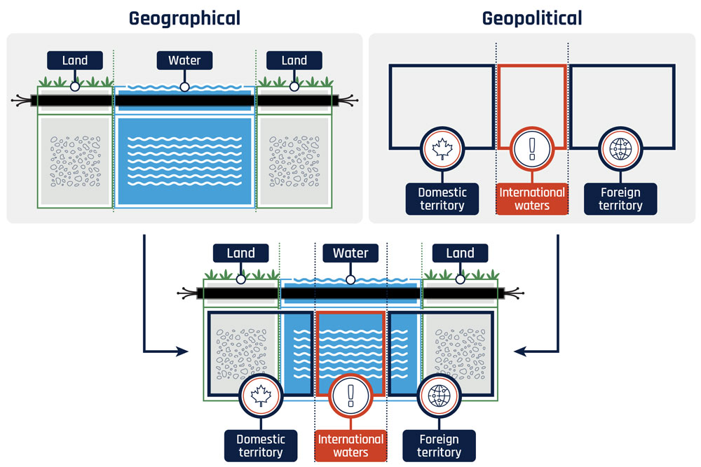
Long description - Figure 1: Geographical and geopolitical domains of submarine cables
Figure 1 depicts the base diagram layout where the submarine cable networks travel between domains. The figure is split into 3 parts to depict the layers of geographical and geopolitical domains overlapping. The first part of the figure presents the geographical domain layout, which shows a rectangular structure that is divided into 3 columns. The 2 outer columns on the diagram represents the land and the column in the middle represents the water. The land sections illustrate soil with grass at the top. The water section illustrates blue ripples. There is a black line illustrated horizontally through all sections signifying the cables passing through all areas.
The second part of the figure presents the geopolitical domain layout, which shows 3 rectangular outlines connected to each other horizontally. The rectangular section on the left represents domestic territory and is identified with a leaf icon. The rectangle in the middle is highlighted in red with an exclamation mark identifying the international waters. The rectangle on the right represents foreign territory and is identified with a globe icon.
The third part of the figure combines the first (geographical) layout in the diagram as the base layer with the second (geopolitical) layout of the diagram layered on top. The diagram has 2 arrows on either side directed downwards from the other parts of the figure to represent the connection between them. The third figure shows the domestic territory rectangular area covering the land and partial water on the left, the international waters rectangular area covering the middle of the water and the foreign territory area covering the land and partial water on the right. The line at the top signifying the cables is presented at the top covering the full length of the diagram with all areas.
Threats can be broken down into 3 categories, including:
- policy and standards threats, such as local, national, and international
- architecture threats, like cyber and physical
- supply chain threats, including third-party risks
The threat surface model in Figure 2 lists key threats in the first and third categories, and shows in more detail key architecture elements that might be vulnerable to threats, including:
- software and systems that control the network directly or remotely
- signal repeaters to avoid signal loss over large transmission distances
- branching units to redirect traffic to different destinations
- multiplexors that split or combine signal paths
- the fibre-optic cables themselves that carry the traffic
- the facilities that house the cable
The model also shows that submarine cable network architectures are not clearly wet or dry; some parts are found both on land and underwater. The cable itself is found in all 3 geographic locations but in different forms, as shown by the cross sections illustrating that in deepest water it is generally much less well-armoured than near shore. Different cable, different risks.
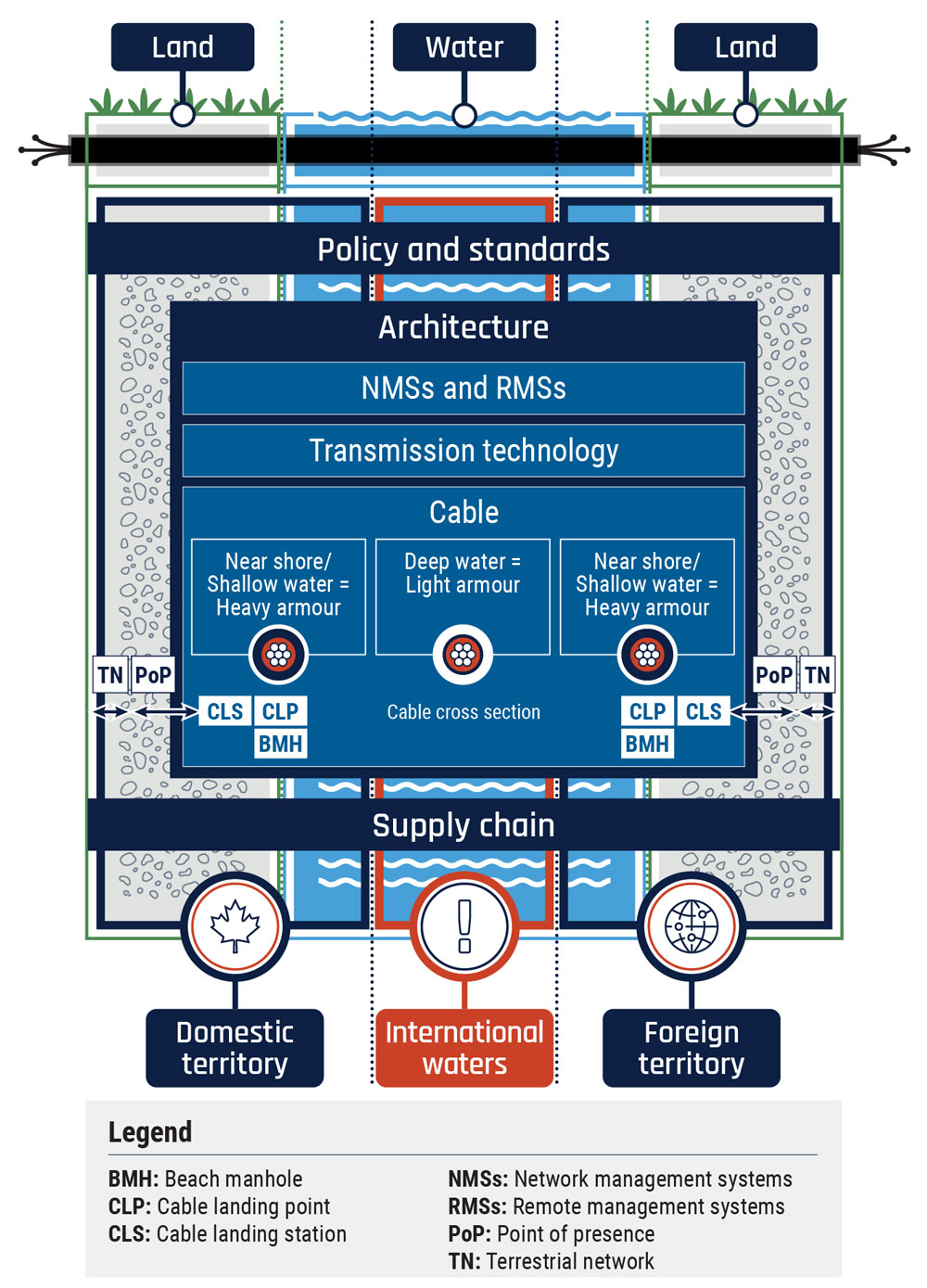
Long description - Figure 2 - Threat surface diagram
The diagram presented for figure 2 is displayed as a square, divided into sections to structure a diagram. The base layer of the diagram presents figure 1, to show the geographical and political domains being impacted. The new layer on top of the figure 1 diagram displays 3 vertical rectangular sections. The first section presents policy and standards, the second section presents architecture and the third section presents supply chain. The section for policy and standards is close to the top, extending the entire width of the diagram. This represents the coverage through all domains (geographical and geopolitical) presented in figure 1.
Directly below the policy and standards section is a large section labelled architecture. This section is displayed in the middle of the diagram, containing 3 boxed sub-headings within its area. From top to bottom, the sub-headings include: network management systems (NMSs) and remote management systems (RMSs), transmission technology and cable. Within the cable sub-section there are 3 cable cross-sections, displayed as 3 boxes horizontally parallel to each other. On the left, the box states near shore or shallow water equals heavy armour with an icon attached that illustrates the cables with a heavy border around it. The second box, in the middle, states deep water equals light armour with an icon attached that illustrates the cables with a light boarder around it. The third box on the right states near shore or shallow water equals heavy armour with the same icon as the first box attached. There are 3 highlighted acronyms displayed below the first and the third box presenting the cable landing station (CLS), the cable landing point (CLP) and the beach manhole (BMH). Below the middle box there is text stating cable cross section. This section for architecture is presented in the center of the figure with a little space open on either side within the land column of the diagram. In this open space there is an arrow directing from the architecture box to another arrow point, directing towards the border of the diagram frame. Above this arrow, there is a highlighted box for point of presence (PoP) presented. The second arrow, to its side and touching the arrow for PoP, is directing towards the frame of the diagram (which extends for the length of the land column). This second arrow has a highlighted box above marking the terrestrial network (TN). These arrows are signifying the PoP and TN connection displayed on either side of the architecture section, extending the full length of the diagram like the other sections within.
The third section, below the architecture section, for supply chain is close to the bottom. This section extends from the far left to the far right of the diagram in the same format as the policy and standards section. This presents the coverage through all domains (geographical and geopolitical) presented in figure 1.
2. Threats and mitigations
Submarine cables connect remote communities and provide international connectivity. They are large data aggregation points for communications and are attractive targets for threat actors. Therefore, it is important to understand and mitigate threats against them.
Threat actors could impact confidentiality, integrity or availability by exploiting vulnerabilities in the systems, processes, suppliers or physical infrastructure that support submarine cable systems, for example:
- threats to confidentiality could include threat actors collecting data and eavesdropping for cybercrime, stealing intellectual property, or conducting espionage
- threats to integrity could include a threat actor causing traffic to redirect, inserting malware payloads, or establishing covert communications channels for data exfiltration or command and control
- threats to availability could include a threat actor causing general or targeted disruption
2.1 Policy and standards threats
The selection of submarine cable locations may be influenced by many factors, including:
- government policy
- regulations
- standards
- land ownership
- business plans
- cost
- physical or geographic restrictions
Threat actors could take advantage of vulnerabilities in policy or standards to threaten submarine cable infrastructure.
There are also geopolitical considerations when a CLP is in foreign territory subject to a different legal framework. Threat actors can take advantage of these factors to influence policies and the location of submarine cables or create dependencies that prevent countries from having the sovereign capability to maintain and operate their submarine cables.
Governments and cable operators should strengthen standards, processes and policies to ensure redundancy and rapid recovery in the event of a cyber incident or physical attack. This can be achieved by having a solid business continuity strategy and a government-wide sovereign communications resilience strategy. To learn more about how to develop an IT recovery plan, read Developing your IT recovery plan (ITSAP.40.004).
For general guidance on what critical infrastructure network operators can do to protect their sector from cyber attacks, read Security considerations for critical infrastructure (ITSAP.10.100).
Policy and regulations: threats and mitigations
Listed below are examples of threat actor scenarios and how they can:
- introduce vulnerabilities to pre-position for attacks by leveraging policy gaps to introduce equipment or services from low-confidence suppliers into Canada's telecommunications networks
- introduce vulnerabilities to pre-position for attacks by leveraging different legal jurisdictions such as cables traversing territorial waters or foreign landing stations
- obstruct licence, permit or review processes to delay or prevent new cable installations or repairs
- prolong outages by using ownership or influence to restrict access to specialized capabilities like repair fleets
- manipulate communities in remote areas that require connectivity but may lack financial resources, technical expertise or risk awareness to implement recommended security controls
- take advantage of publicly disclosed information, such as cable tracking websites and environmental impact and permit registries to conduct reconnaissance and geolocate target infrastructure like submarine cables, cable clusters, CLPs and cable landing stations (CLSs)
- leverage an over-reliance on a particular submarine cable by threatening to cut or deny service to a community during time of conflict or political disagreement
Listed below are examples of mitigations measures to take:
- Understand foreign and local laws, policies and business practices that may affect cable locations, cable access, data privacy and license and permit requirements, for example consider route and CLS geodiversity
- Ensure that change-management processes include monitoring and auditing changes at cable sites or any third-party access
- Facilitate cooperation among submarine cable and infrastructure owners/operators and appropriate agencies to share threat information in a timely manner and take special recommended actions during times of conflict or tension to prevent or reduce the impact of compromises. The Canadian Security Telecommunications Advisory Committee (CSTAC) is a good example of an industry forum facilitating cooperation among entities
2.2 Architecture threats
Architecture threats refer to vulnerabilities within the design or structure of a system that threat actors can exploit to cause harm. In submarine cable system architecture, threat actors could take advantage of both cyber and physical weaknesses within the system.
2.2.1 Cyber architecture
The network management system and remote management system (RMS) are connected devices, with control over the system, and are susceptible to conventional cyber threats. They have network connectivity, which may be accessed remotely and can change the behaviour and security of the cable deployment. A threat actor could exploit software or configuration vulnerabilities to cause disruption, manipulate traffic or facilitate eavesdropping of communications.
Threat actors may use malware, phishing or weak passwords to gain unauthorized access to network equipment. If they bypass authentication and access the network, this can lead to:
- loss of confidentiality, integrity and availability
- denial-of-service attacks against other systems
- border gateway protocol redirect attacks
2.2.1.1 Suggested mitigations
Operators should implement a zero-trust approach to security architecture and implement security best practices, including defence-in-depth. The following list provides additional mitigations measures that should be applied.
- Establish, use and regularly review validated cyber hygiene best practices, such as:
- implement the principle of least privilege and give personnel only the access required to perform authorized tasks
- change vendor-supplied default credentials
- use multi-factor authentication on all user accounts
- Periodically collect and analyze small portions (or samples) of data to monitor, report, investigate, and remediate incidents to contain compromise
- To learn more, read the following guidance
- A zero trust approach to security architecture (ITSM.10.008)
- Cyber security hygiene best practices for your organization (ITSAP.10.102)
- Developing your IT recovery plan (ITSAP.40.004)
- Guidance on defence in depth for cloud-based services (ITSAP.50.104)
- Security considerations for critical infrastructure (ITSAP.10.100)
2.2.2 Physical architecture
From a physical perspective, submarine cable architectures are vulnerable to threats because they:
- are generally unmonitored, allowing for unsupervised or unauthorized access
- may be located in remote locations
- extend over long distances with many points of access
A threat actor could seek to exploit a physical vulnerability to cause disruption, tap and collect telecommunications or modify cable traffic. A significant impact may result if threat actors focus on choke points where multiple cables converge or target regions lacking redundancy, such as remote communities.
Submarine cable operators should implement physical security best practices to protect:
- cables
- beach manholes (BMHs)
- CLPs and CLSs from unauthorized access
- physical attacks or natural disasters
They should also build a resilient architecture that incorporates robustness, redundancy and security by design. To build a resilient architecture, read the Cybersecurity and Infrastructure Security Agency's (CISA) secure-by-design publication Secure by Design.
For more information on secure by design, read CISA's Secure by Demand: Priority Considerations for Operational Technology Owners and Operators when Selecting Digital Products and the Australian Signals Directorate's Choosing secure and verifiable technologies.
2.2.2.1 Physical architecture: threats and mitigations
Listed below are examples of threat scenarios.
- Marine activity or natural disasters such as earthquakes, ship anchors or fishing operations accidentally cut cables or damage components
- A threat actor intentionally cuts cables or damages components as an act of open vandalism or covertly under the guise of normal operations such as fishing, laying cables, or servicing
- A threat actor uses physical access to CLSs or CLPs to alter or manipulate equipment
- A threat actor uses sophisticated techniques in deep water, such as submersibles or commercial-grade fishing infrastructure, to physically damage fibre-optic cables
Listed below are examples of mitigation measures to take.
- Consider designating visibly enforced protection zones where certain behaviours are policed and criminalized
- Consider conducting and automating continuity tests to verify the integrity of the cables
- Consider conducting random site visits to validate cyber practices firsthand, identify maturity gaps and drive accountable improvements that increase cyber maturity and diligence
- Consider redundancy strategies from a national security perspective, which may differ from an operator's recovery plan
- For more information, read
- the Royal Canadian Mountain Police's policy instruments, guidelines and tools related to physical security
- the CSTAC's Telecommunications Network Resiliency in Canada: A Path Forward (PDF)
2.3 Supply chain threats
Threat actors could seek to exploit a weakness at any stage in the supply chain lifecycle to alter the intended functionality of submarine cables, cause disruption or eavesdrop on communications. In cyber security, every link in a global supply chain can pose a threat. Strengthen your organization's cyber security defence by identifying, assessing and mitigating the risks associated with information and communications technology products and service supply chains.
Submarine cable equipment and services are provided by a range of suppliers. Cable operators should implement a supply chain risk management program to assess supplier confidence as part of the procurement process. They should also aim to use suppliers where the risk exposure is considered acceptable whenever possible, especially for critical infrastructure deployments. If operators need to use a supplier in which they have lower confidence, they should use additional mitigation strategies to address the elevated risk exposure.
2.3.1 Supply chain: threats and mitigations
Listed below are examples of threat scenarios.
- Organizations procure equipment or services from low-confidence suppliers, increasing the likelihood of intentional or accidental vulnerabilities
- A threat actor covertly adds a vulnerability to hardware or software from any supplier, exploiting weaknesses at any stage of the supply chain lifecycle
- A threat actor compromises a trusted managed service provider, then uses stolen credentials to access restricted buildings, resources or systems
- Trusted repair or maintenance crews may not be available to fix failed or damaged equipment and supervision may not be possible
- Co-locating any equipment at CLSs could allow unanticipated physical access to untrusted managed service providers
Listed below are examples of mitigation measures to take.
- Establish, use, and regularly review a robust supply chain risk management strategy, emphasizing the use of validated best practices and forward-looking zero-trust principles, as well as tools like software and hardware bills of materials
- Obscure point of presence locations with robust physical and cyber security measures
- Regularly research and review suppliers and use security clauses when procuring equipment and services. For example, consider roles of nation-state threat actors controlling installation, upgrade and repair fleets, materials, patches, etc.
For further information and recommendations, read the following guidance:
Effective date
This publication takes effect on October 1, 2026.
This is an unclassified publication under the authority of the Head, Canadian Centre for Cyber Security (Cyber Centre). For more information or to suggest amendments, contact the Cyber Centre:
email contact@cyber.gc.ca |Mobile 613-949-7048 or 1‑833‑CYBER‑88
Revision history
- First release: October 1, 2026